Alexandr A.Shpilman (alexandrshpilman78@gmail.com )
The Converter-U
Article beginning in 1N12, 1N13 , 1N14 , 1N15 , 1N16 , 1N17
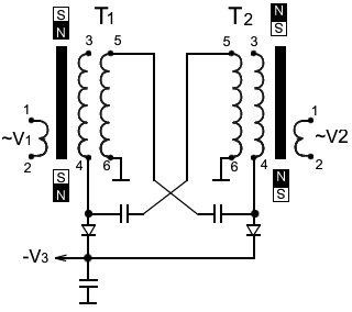
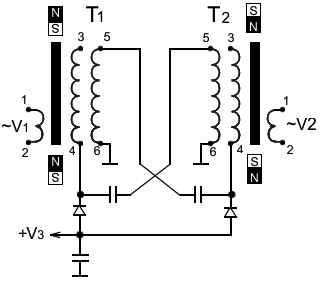
In the constructions described in 1N17, assembled according to the scheme shown in Fig.1, the pseudo-positive component of the "axion field" is activated. Assembled according to the scheme shown in Fig.2, the predominantly pseudo-negative component of the "axion field" is activated.
|
|
|
|
Fig.1 |
Fig.2 |
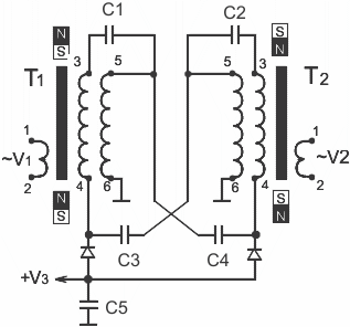
Probably, this difference is caused by the direction of counter currents in the coils when the electric capacitors are recharged between windings of these coils. The magnitude of these currents can be increased by introducing additional capacitors C1 and C2, as shown in Fig.3.
|
|
|
|
Fig.3 |
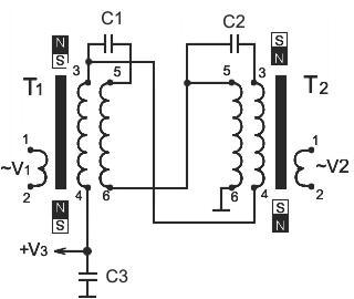
Fig.4 |
On Fig.4 shows a
variant of the circuit where T1 is the generator of the predominantly
pseudo-negative component of the "axion
field". And T2 is the generator of the
predominantly pseudo-positive component of the "axion
field". Taken together, the device becomes a source of "axion field" balanced by component. We will name it: "Converter-G".
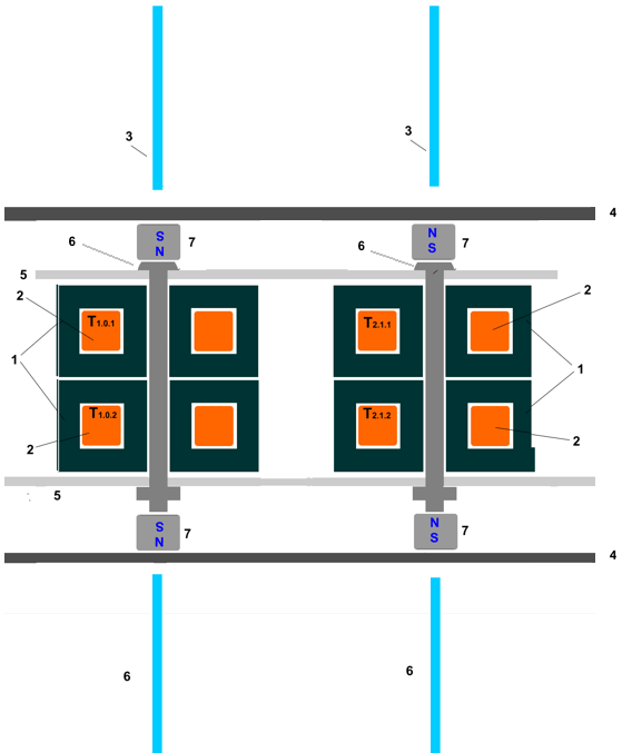
The design of the described circuits is shown in Fig. 5, where in the ferrite cups 1, the coils 2 are connected according to the scheme Fig. 3 and Fig.4. The iron bolts 6 and the plates 4 close the magnetic field circuit of the permanent magnets 7. This provides the necessary magnitude and direction of the magnetic vector potential. Aluminum plates 5 provide a heat sink and partly close the generated "axion field" inside the device, thereby increasing the field density in the active zone.
|
|
|
|
Fig.5 |
Fig.6 |
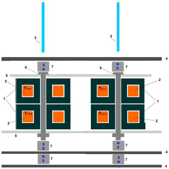
The problem with the construction depicted in Fig. 5 is that along the axis of the ferrite cups narrow multidirectional beams of the "axion field" (3 and 6) of large penetrating power are formed. Lock these rays can be added to the design of a couple of magnets 7 with an iron plate 4, as shown in Fig.6.
