Alexandr A.Shpilman (alexandrshpilman78@gmail.com )
The Converter-NQ
Article beginning in 1N12
Earlier converters seen as
manipulators DSS elements. What if a similar scheme to apply
to change the properties of the nuclei of ordinary atoms? Try to translate the latest in state of the DS?
Protons, the
"core" of atoms no balls-suns in the center of the atom. (For
example, talking about this property "Foucault currents"). Protons, the "core" of the
atoms have a spatial structure far beyond the atom (the size of a hydrogen atom
alleged order of 10^-8 cm emits and absorbs quanta of the electromagnetic field
with a wavelength of 21 cm without loss, ie the
difference in nine orders, a billion time). Have both DSS and pseudo positive
elements and pseudo negative of the components (spatial structure of quarks
with positive and negative charge). Once these components are
not split in space and usually have a very small extent (compared to DSS
elements). Therefore it is necessary to modernize the design described the
article "The Converter". The latest proposed the
following model:
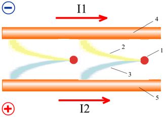
Pseudo-positive a
component 2 of DSS an element 1 is guided towards a conductor 4 having negative electric potential (the Fig.1 see). And pseudo-negative a component 3 is guided
towards a conductor 5 having positive electric potential.
|
Fig.1 |
Fig.2 |
If we pass now through conductors 4 and 5 electric current I1 and I2 as it is shown in a Fig.2
"pseudo-charged" components of DSS elements, being extended towards to
a direction of an electric current, will start to merge in two dense plaits.
The proposed option is instead Fig.2
have Fig.3. In conductors 4 and 5 electric currents I1
and I2 have the same orientation.
|
Fig.3 |
|
Fig .4 |
The question arises as
"pump" energy components 2 and 3 of the proton?
One option - increasing the electrical potential difference U between
the conductors 4 and 5, we increase splitting between the components 2 and 3,
in consequence of which increases the internal energy of the proton (for many
physicists this shocking statement), respectively, and increases its mass (E=m*c^2).
Now if we change the direction of the electric currents I1 and I2 in the
opposite direction (on Fig.4 at time t1, where the upper diagram the change in
voltage between the conductors, the lower the change of currents in them), then
by self-induced increase internal impulse of components 2 and 3, even adding
the internal energy of the proton. Then reduce the voltage U between the
conductors 4 and 5. The splitting between the components 2
and 3 protons decreases. Reduced internal energy and the mass of the proton,
and if we change direction electric currents I1 and I2 to the opposite again
(at time t2), then by self-induced decrease internal impulse of components 2 and 3 is less than it has increased for the first time.
This way you can pump up the components 2 and 3 until they spread on numerous
larger width than the distance between the conductors 4 and 5. (The idea is
similar to the idea of acceleration Sputnik-shaped dumbbell. At the apogee of
its orbit sphere dumbbells shift, and at perihelion
move apart.)
If you choose two twisted copper
wires in the silk insulation diameter of 0.2 mm, then alternating of current in
the conductor 5 can be chosen at 300-400 mA (see middle chart on Fig.4). The
electric conductor 5 is relatively conductor 4 have
pulsation voltage swing of 160-200 volts. If the swing of change in the current
I1 to choose half (unipolar, pulsed current), the pseudo negative component 3
acquires more energy than pseudo positive 2. As a result, the device generates
a field that is less scattered around. Becomes more dense, stable. Takes on new physical properties that
are yet to be explored.
If an additional electrical conductor 5 on the conductor 4 apply dc constant voltage U0
= +300 volts then the generated field is concentrated mainly in the device. Its
density increases, it is tempting for physical experiments. The effect is enhanced if the twisting wires 4.5 put in cups of
ferrite.
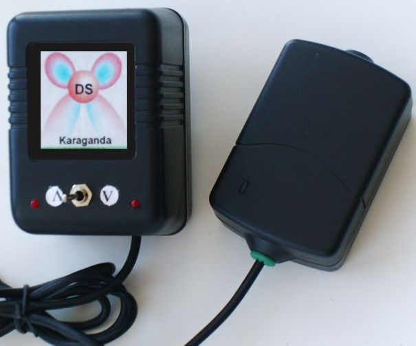
At Photo 1 shows the appearance
Converter-NQ with its emitter.
In "Some
effects" are the first observation of the device.
|
|
Even in experiments with generator "Linear
accelerator - the source of the axion field"
noted:
"Tried to shift the phase change of the voltage across the
electrodes and the magnetic field in the ferrite tube and found that, the
maximum intensity of the "axion field" is
achieved at phase changes in electrical potential across the electrodes with
the phase of the EMF of self-induction of the toroidal
coil. That is, there is a direct flow acceleration Z1 via EMF coils, and the
voltage on the electrodes only deflects the beam in the desired direction. In
this connection was made generator shown in Fig.1.
On conclusions of electrodes 3 and 4 the squared alternating voltage with
amplitude in 12V moved, and on electrodes 1,2 toroidal windings inphase
submitted sinusoidal voltage amplitude 36-45V (12-15V/round)."
From idea
Converter-NQ already a little in a different way sees operation of the
generator described in "Linear accelerator -
the source of the axion field". During too
time experience of experiments with the generator says that is important not
only change of a current, but speed of its change is
still important. I.e. it is necessary to reach the greatest possible value of
EMF of a self-induction. For the described EMF generator of a self-induction
should be higher than 12-15V/round.
From this requirement Converter design seems
somewhat different, such as Fig.5 shows. Where in the ferrite tube 5 with two
electric facings - iron tube 4 and 6 of the aluminum foil with a vertical
incision exclusive "coiled-circuit currents." Outside the tube is wound on a ferrite electric coil in two layers 8 and 9.
Separated by a dielectric spacer 7. Tube coil 8 is connected to the outside 9, via a conductor 10, for uniform distribution of the
electric field between layers. Through the wire 1 on
iron tube 4 is a negative pulsed electric potential (300-350V) as shown in the
top graph Fig.6. It is important at times t2, t4, t6, ...
to achieve the highest possible discharge voltage on pin 2 relative to pin 3
and 1. Specifically, the most important to achieve the highest possible interturn voltage.
|
|
|
|
|
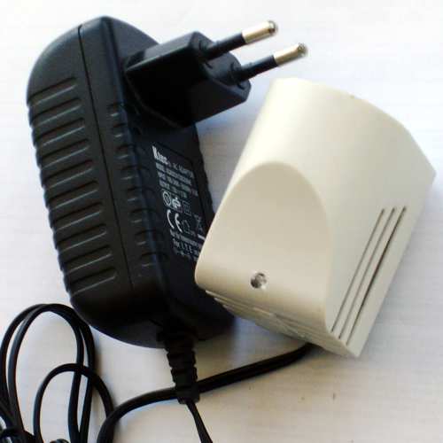
In Photo 2 shows the appearance Converter-NQ2.
If iron pipe 4 insert an iron rod, the outgoing beam from the Converter
becomes more dense. External ferromagnetic materials
also strongly influence the shape of the beam.
|
|
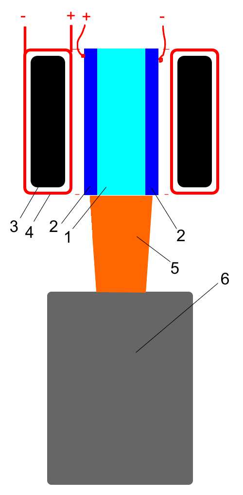
In addition to the generation of a field purely
electric currents can be used and the light flux. For example in Fig.7
transparent dielectric 1, penetrates the flow of light 5 of laser 6. Dielectric
1 concluded between two aluminum plates, the voltage between which induces an
electric field perpendicular to the light flux. The function of this field is
similar to that shown in Fig.1. Electric coil 4 with a ferrimagnetic
core 3 sets the magnetic vector potential to meet the luminous flux that
defines the spatial orientation of the generated "axion
field" Type 2 (see "Physical
properties of axion (spin) fields"). The
advantage of the design is the simplicity of its electronics.
On the basis of new ideas can adjust the device described in
the article "The Optical
Generator Axion (Spin) of a Field".
|
If you wish to make the experiments, but are at a loss
in independent manufacturing of the Converter, you can order its
manufacturing. Information on E-mail: alexandrshpilman78@gmail.com |