Alexandr A.Shpilman (alexandrshpilman78@gmail.com )
The Converter-U
Article beginning in 1N12 , 1N13
In the development of design
Converter-NQ has an interest to simplify the electronics, in some loss of
efficiency to compensate an increase of multiple in the frequency voltages and
currents used in the coils. Simplifying, we reduce the idea shear sinusoidal
varying self-induction voltage on the two wires of approximately 90 degrees
with respect to the voltage between them. (In theory, the addition of higher
harmonics can enhance the effect.) This can be achieved using two oscillating
circuit as Fig.1.
|
|
|
|
|
Fig.1 |
Fig.2 |
Photo1 |
One oscillating circuit - inductance
coil of the transformer T1 and capacitor C2 between the windings of the
transformer T2. The second oscillating circuit - inductance coil of the
transformer T2 and the capacitor C1 between the windings of the transformer T1.
These oscillation circuits out of phase electrical oscillation can be arbitrary
(but we need about 90 degrees).
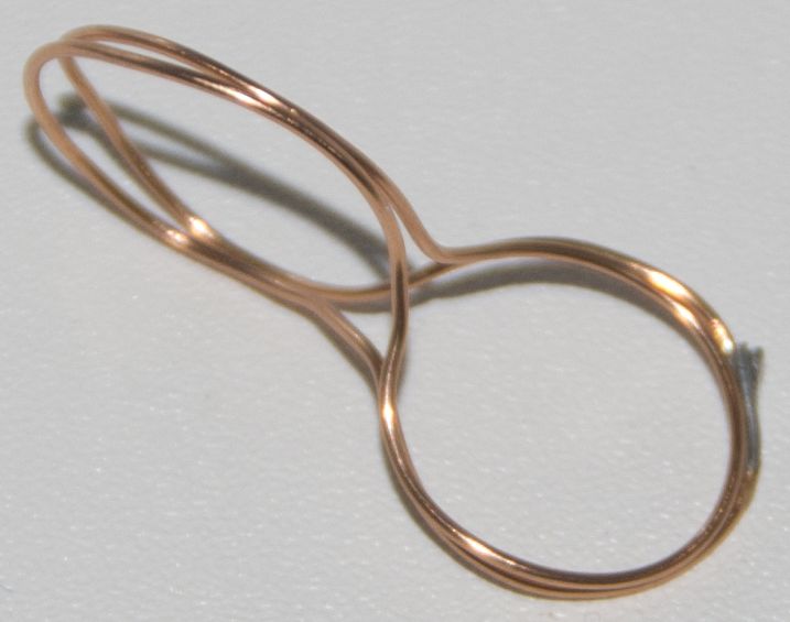
For high frequency circuit may look
like as shown in Fig.2 and Photo1. It is interesting that the wire ring, curl
into a figure in Photo 1, gives unusual sensations in their hands. Perhaps it
works on similarity the designs described in the "Passive Resonators Axion
Fields".
For preliminary splitting
pseudo-positive and pseudo-negative components of the DSS elements necessary to
set the bias voltage Vsm between the windings T1 and
T2. For this in scheme adds capacitors C3 and C4, as shown in Fig.3.
|
|
|
|
|
Fig.3 |
Fig.4 |
Photo 2 |
Must be set in the coils and bias current for pre-orientation of the
pseudo-positive and pseudo-negative components of DSS-elements.
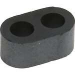
This point could seriously
complicate the circuitry. For relatively not higher frequencies, the problem
can be solved by using a ferrite core transflyuktor
(see. Fig.4). In particular, replacing the bias current in the conductors of
the coils to the action of the vector magnetic potential additional electrical
coil.
|
|
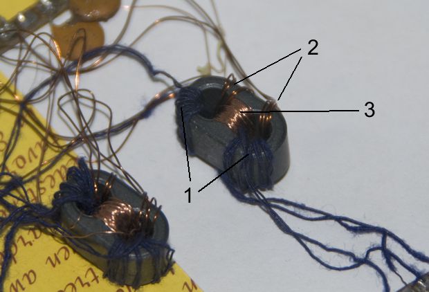
In Photo 2, double wire wound coil
transformers 1 (Figure 1) and 2 turns of excitation of oscillations in the
oscillatory circuit. Are included so that high-frequency vibrations are not
excited in the coil magnetization 3, creates a magnetic vector potential
desired direction.
It is worth noting that at this
stage of perfection is lost symmetry of the circuit and it is necessary to
align the phase of electrical oscillations in circuits with the direction of
the magnetic vector potential.
Fig.5 shows the further development of circuit with Fig.3. The
capacitors C1, .., C4 in Fig.3 are replaced by the
circuit in Fig.5 the capacitance between the twisted wires of adjacent
oscillating circuits. Through a resistor R1, R0, R1 bias voltage is applied on
the rise.
U2 = U0 + Vsm = U-1
+ 2*Vsm
Number of stages oscillating
circuits can be arbitrary and thus its resonant frequency will vary slightly.
End "half-circuit" are connected with each other in the ring circuits
through capacitors (decoupling voltage difference). To create the desired
magnetic vector potential can also be used a ferrite core transflyuktor
with coil bias.
In this scheme, one can expect a significant additional effect of
splitting component of DSS elements.