Alexandr A.Shpilman (alexandrshpilman78@gmail.com )
The Converter-U
Article beginning in 1N12, 1N13 , 1N14
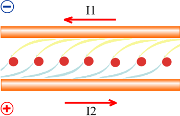
The circuit shown in Fig.5 in the article 1N14 has a drawback such that due to the
unbalanced capacitive coupling between the windings, getting stronger
interaction of two resonant circuits together. That will require a hard drive
to their electrical oscillations phase-shifted by 90 degrees.
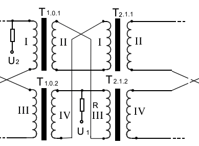
This shortage is deprived of the circuit shown in Fig.1:
|
Fig.1 |
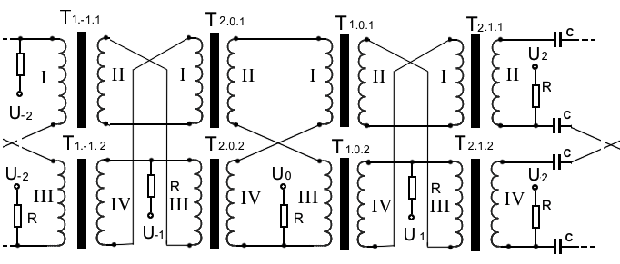
Where the windings I, II and III, IV twisted together in pairs. There
are two types of ferrite cores transflyuktor T1 and
T2.
T1.x.1 and T1.x.2 - this winding in two
different windows transflyuktor T1.
T2.x.1 and T2.x.2 - this winding in two
different windows transflyuktor T2.
Sections may be arbitrarily many. That allows consistently enhance
cleavage component DSS elements due to the rising of the electric potential at
each subsequent section.
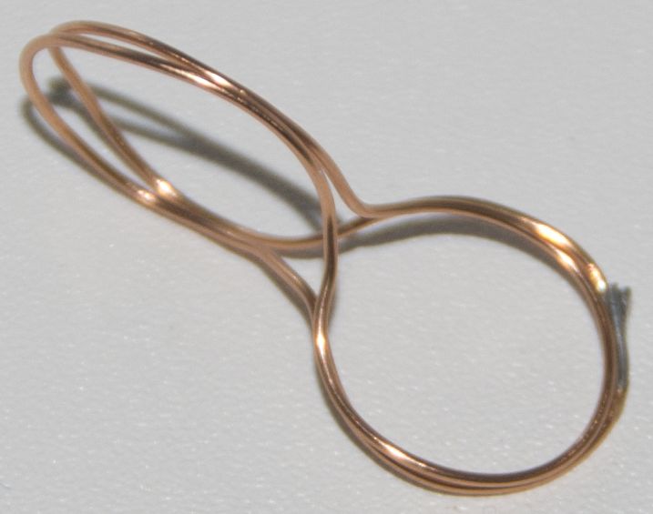
Wires in the circuit a lot. Connect them easy to get confused. A
simplified version in Fig.2.
|
Fig.2 |
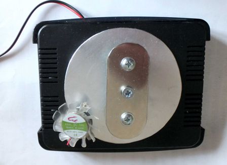
Photo 1 |
Photo 2 |
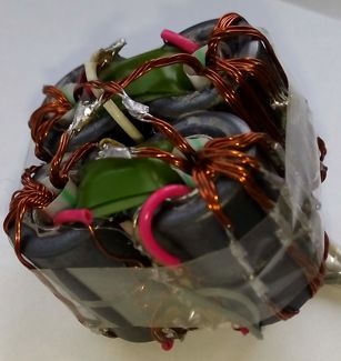
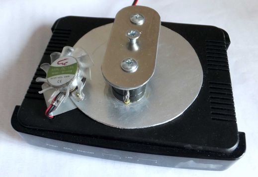
Transflyuktors composed of two pairs of ferrite
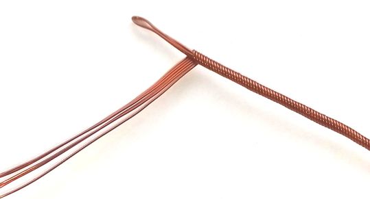
tubes (see Photo 1). The coils are wound wire twisted as
shown in Photo 2. External sheath of the windings I, III
transflyuktor T1, and coil II, IV transflyuktor
T2. A core winding is I, III transflyuktor T2, and
windings II, IV transflyuktor T1. In the last
positive voltage (U1) relative the braid (U2).
Bias winding and excitation (the red wire on Photo.1) oscillations in
the resonant circuit are not shown. Bias winding on Photo.1 covered with green
insulation tape.
To improve the efficiency bias coils, inside the ferrite tubes inserted
iron tube. This can significantly increase the value of the magnetic vector
potential along the axis of the ferrite tubes.
At work the device, formed two opposite to the direction of the beam
along the axis of the ferrite tubes.
When applying a negative voltage on the bias winding on the wire relative
to the sheath Photo.2, ray density increases. This means that the design of the
wire harness shown in Photo.2 not provide adequate emptive
"acceleration" pseudo-negative component of "axion
field" beam.
To increase the effectiveness of "acceleration" pseudo-negative
component of "axion field" beam in the
equipotential (the variable component) points to the open circuit windings are
connected capacitors C, and current sources I1, I2, through chokes Dr (see Fig.3). Thus, in the bundles of the windings is
given a counter current, the changing nature of the bundle of pseudo-negative
and pseudo-positive component of "axion
field" as shown in Fig.4 (see Converter).
|
|
|
|
|
Fig.3 |
Fig.4 |
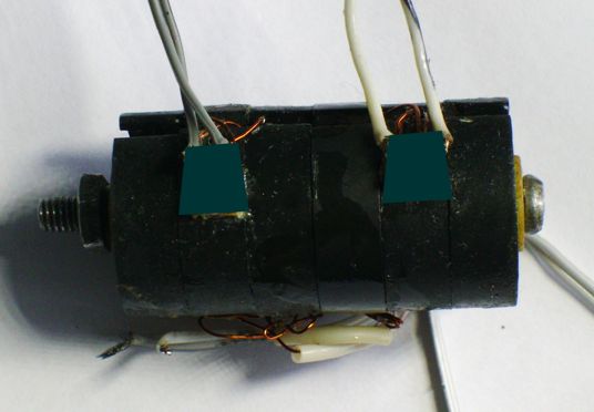
Photo 3 |
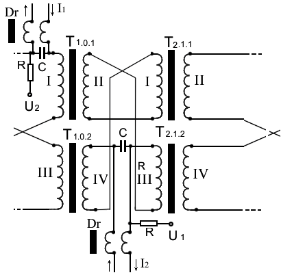
By specifying the required ratio of the currents I1, I2, can eliminate
the use of the bias winding. That gives a lot of opportunities. In particular,
in the construction shown in Photo.3 can replace the solid wire for a coaxial
cable with the sheath and commutate central conductor cable according to the
scheme shown in Fig.3. Instead of the coaxial cable may be a strip line. What
makes a tempting option to make the entire circuit on a single substrate
"PCB."
In principle, this design idea does not exclude an additional use
magnetizing coils and / or permanent magnets, with the same purpose.
The design shown in Photo.1 creates in the environment are two of the
beam of the "axion field". This reduces the
density of "axion field" in the active
zone. Naturally the desire to try to concentrate the entire field in the active
zone of the generator. Reduced to the minimum possible dispersion of the "axion field" in the surrounding space. To do this replace
the ferrite tube on ferrite cups, both in design on Photo.4. Ferrite cups
orient them so that the magnetic field of the bias currents formed in the iron
rod of bolt that tightens the cup in a single cylinder.
At work the device inside of its center,
formed a ball of "axion field". By
increasing the bias currents, its density increases. The density of the ball
increases and an increase in the magnetization of the iron rod external
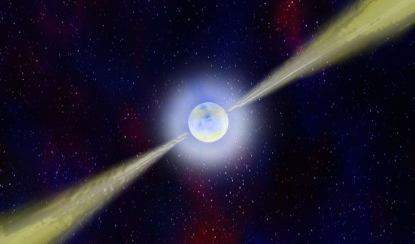
permanent magnet. In addition to the ball, along the axis of the device is
formed by two bottlenecks dense beam of the "axion
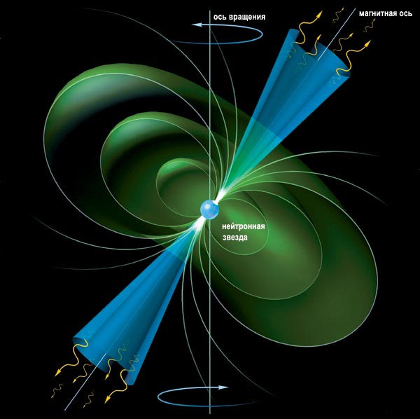
field". On the likeness of the image shown in Fig.5 of the neutron star.
Probably formed the "axion field" type 5 (see Ring
Structures of "Axion Fields"). And
probably we have a close analogy with a neutron star. Because the
device increases the energy / mass of pseudo-negative components of the proton
(d quark?) DSS elements. And
pulls together "axion field" into a dense
ball and rays a kind of the nuclear strong force.
|
|
|
|
|
Photo 4 |
Fig.5 |
Fig.6 |
The device surrounds the ball less
dense "axion field". The density gradually
decreases with increasing distance. At large distances (compared with the size of
the device), the spherical shape is transformed into a toroid, on the
similarity shown in Fig.6. Feels the slow rotation of the toroid field around
the tool axis, wherein for the human, the field itself does not cause negative
sensations.
In particular, the likely effectiveness of the device has a dependency:
P ~ UV*UP = UV2
* n
Where
UV - interturn coil voltage
UP - the amplitude of the AC voltage between windings
n - the number of turns in the coil.
At small sizes characteristic of DSS elements are likely to become an
important self-inductance of the electric field:
EV = UV / D
Where
D - average diameter of the turns of the coils.
Then we have:
P ~ UV2 * n /
D
Consequently, primarily plays the major role coiled coil EMF. It
increases by increasing the cross section of the ferrite core and increasing
the frequency (up to a certain limit). But this leads to intense heating of the
core, so important is the heat removal. Moreover, the electric wire coil is
also heated.
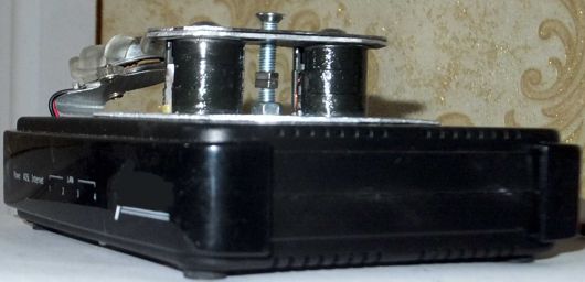
Thus, the design of the device is shown in Photo.4 transformed into the
design of the device shown in Photo 5-6 and Fig.7.
|
|
|
|
Photo 5 |
Fig..7 |
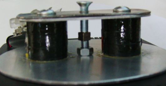
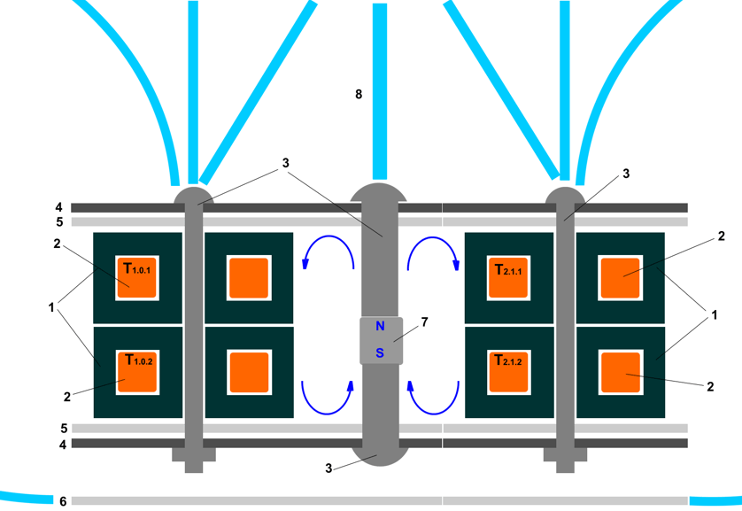
Fig.7 in the ferrite cups 1, coils 2 are connected by the scheme Fig.3. Iron
bolts 3 and the plate 4 closes the circuit of the magnetic field of the
permanent magnet 7 as shown by arrows blue. This provides necessary value and
direction of the magnetic vector potential.
In operation, the device is formed by three beam "axion field" 8 emanating along the axis of the bolts
3. Part of the radiation merges into one central. This results in a
distribution of the picture of the "axion field"
like Fig.6. The only aluminum plate 6, significantly limits the downward
radiation drawing/unit. Aluminum plate 5 provides heat removal from the ferrite
cups 1 and at the same time transferred a considerable part of radiation in the
horizontal plane.
|
|
|
|
|
|
Photo 6 |
|