Alexandr A.Shpilman (alexandrshpilman78@gmail.com )
The Converter-U
Article beginning in 1N12, 1N13 , 1N14 , 1N15
In the circuit shown in Fig.1, EMF
electrical oscillations to T1 and T2 are shifted in phase as shown in Fig.2.
But, in theory, would be more effective option as shown in Fig.3, where the
transition process occurred on the same transformer with a constant maximum of
EMF in another transformer. This requires a certain way to mix the third
harmonic to signal. Only as far will be justified complication of an electrical
circuit?
|
|
|
|
|
Fig.1 |
Fig.2 |
Fig3 |
In a further development of the device will change magnetic biasing circuit. Previously:
|
|
|
|
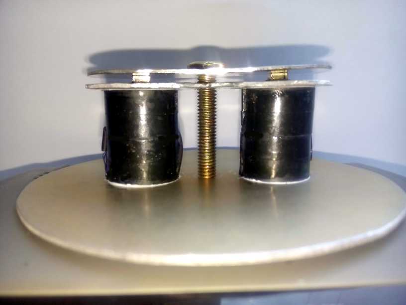
Photo 1 |
Fig.4 |
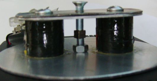
Fig.4 in the ferrite cups 1, coils 2
are connected by the scheme Fig.3. Iron bolts 3 and the plate 4 closes the
circuit of the magnetic field of the permanent magnet 7 as shown by arrows
blue.
Advanced:
|
|
|
|
|
|
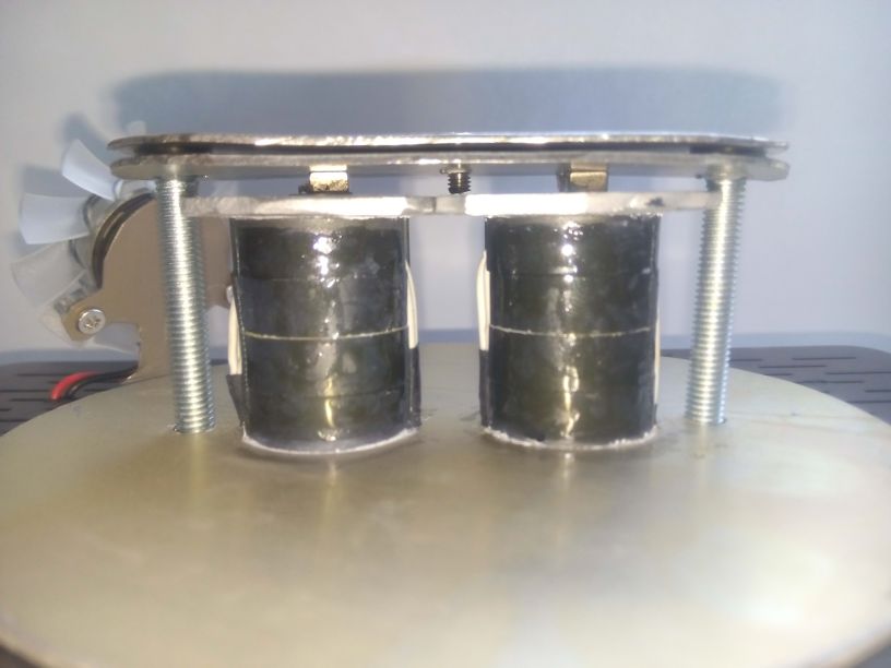
Shown in the picture, the change in position of the magnets 7, partly
fulfilled the role of "cork". Limited ejection the "axion
field" on the T1 and T2 axis, thereby increasing the converter efficiency.