Alexandr A.Shpilman (alexandrshpilman78@gmail.com )
The Converter-U
Article beginning in 1N12, 1N13 , 1N14 , 1N15 , 1N16
The use of permanent magnets of bias
makes it possible to simplify the "Converter-U"
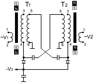
scheme shown there in Fig.1. In the
design in Fig.1 windings 34 and 56 are wound with a double strip of copper
foil, which are isolated from each other by an insulating gasket. The
inductance of the winding 56 of the transformer T1 with the electric
capacitance between the coils 34 and 56 of the transformer T2 forms one
oscillatory circuit. The inductance of the winding 56 of the transformer T2
with the electrical capacitance between the coils 34 and 56 of the transformer
T1 form a second oscillatory circuit. In these oscillatory circuits, electric
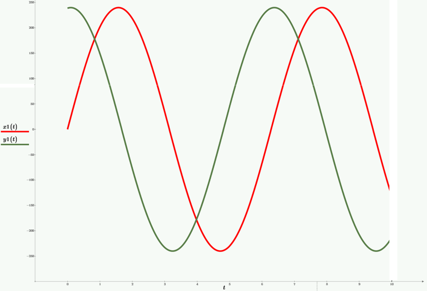
oscillations are excited, by applying AC voltage V1 and V2 to windings 12,
transformers T1 and T2, with a phase shift of 90 degrees. Since this is shown
in Fig.2.
|
|
|
|
|
Fig.1 |
Fig.2 |
Fig.3 |
V3 specifies the negative bias
voltage on the windings 34 of the transformers T1 and T2.
One of the options for implementing this scheme:
Transformers T1 and T2 use ferrite cups M1500HM3-2 Ч18. Windings
34,56 have 8 turns. At a voltage of 25-30 V/turn, the voltage amplitude at the
contact 5 of the winding 56 reaches 200-240 V, at a resonant frequency of
700-800 kHz. Voltage V3 is adjustable in the range of -90, -120 V.
With such parameters, the ferrite cups become very hot, therefore it is
necessary to use radiators for heat removal and the AC voltage V1 and V2 must
be switched on for a short time, with a frequency of several Hz, with a duty
ratio of 6 or more.
The correct work of the converter depends on the winding direction of
the coils, the orientation of the permanent magnets and the correct choice of
the sign of the phase shift between the AC voltages V1 and V2.
The construction shown in Fig.1 creates a dense "axion field"
in the form of a ball around the device and/or the beam emanating from it.
(Depends on the design features.) Probably, the pseudo-positive component of
the "axion field" is activated.
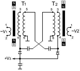
If, as shown in Fig.3, in the design to change the polarity of magnets,
diodes and V3 to give positive polarity from +90 to +160 V, then the quality of
the "axion field" of the device will be similar to " Converter-NQ3 ", having a large
penetrating ability. Probably, the pseudo-negative component of the "axion
field" is activated.


