Alexandr A.Shpilman (alexandrshpilman78@gmail.com )
Prelude
The "dark
matter" of astrophysicists exists not only somewhere far away, but
certainly around and inside us. These tracks (Photo 1-5) in the recording media
(observations of nuclear reactions) were observed approximately some
experiments with high-voltage discharges. In fact, there is no official opinion
on the nature of the phenomenon.
DSS matter is a matter
that has a momentum of movement in time other than that of ordinary matter.
This matter has a different spectrum of the wave function in the space of
time. It is little manifested in
our time gap "now". DSS matter can turn into ordinary matter if it
falls into the gravitational pit of our "now". In this case,
theoretically, up to 103 GeV of energy can be released from one
"manifested" proton. If this is an atom with 100 nucleons in the
nucleus, then all 105 GeV. This is approximately equal to the energy
of the tracks shown in Photo 1-5.
|
|
|
|
Фото
1 |
Фото
2 |
|
|
|
Фото
3 |
|
|
|
|
Фото
4 |
Фото
5 |
In the vicinity of the
recorded tracks there were chemical
elements, which were previously absent there. The experiment
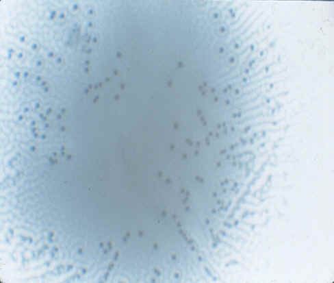
of M. Sue Benford on the irradiation of the X-ray
film with an "axion generator" recorded on the film constantly
evolving distinctive "spots" and "traces" like tracks of
charged particles in an emulsion (Photo 6).
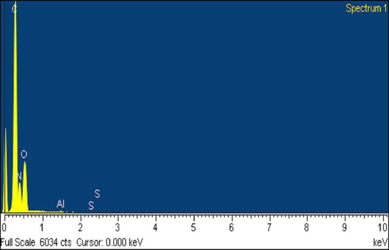
Were there any changes in
the surface emulsion that could interfere with the bleaching process on the
X-ray surface? For this purpose analysis of the X-ray
images was performed using a JSM-820 - Scanning Electron Microscope (SEM). The
results show that the exposed areas (with spots and traces) contain an
insignificant amount of sulfur, magnesium and aluminum (Graph 1, Tab.1);
Despite the fact that, the main area contains only carbon, nitrogen and oxygen.
|
|
|
|
|
Фото
6 |
Граф.1 |
Таб.1 |
The thought leads to the
DSS elements and the appearance of two
tracks converging at one point, and in the same phase of the "tractor
track" (Photo 3b, Photo 4). The last is very important argument.
It can be assumed that
there is DSS matter, which manifests itself noticeably in our time gap
"now". It was known from the earliest times as manna, Qi, and now
fashionable - "subtle energy", "subtle matter". Even more
DSS of matter exists around us and practically does not manifest itself in the
"now" (that's why it is preserved). High-voltage processes (for example,
lightning) and some other specific situations can bring it out of a state of
collapse like.
The most successful of
high-voltage devices can be considered a generator type IPP-2, IPP-4.
|
|
|
|
|
|
Рис.1 |
Фото
7 |
Рис.2 |
Рис.3 |

The design consists of
two identical ionizers I and II (see Figure 1). Each of them consists of dielectric
tubes 11 and 12. The tubes are made of aluminum foil 1 and 3. They are mounted
on one axis with a gap between them of 3-5 mm. The electrodes are located
inside the tube. The electrode 4 is placed in a dielectric tube 7.
A pulsating voltage of
+30 kV is applied to the electrode 1.
A pulsating voltage of 45
kV is applied to the electrode 3.
The electrode 4 has a
zero potential.
The vector potential of
the spiral structure (Fig. 3, as described in the "Simulator" of the
"IPP-2" power station)
creates two toroidal electric coils 10 and cylindrical 9 wound
on the iron rings 8 that are put on the dielectric tubes 11 and 12.
The corona discharge on
the pointed edge of the aluminum foil tube 1 (upper in the figure) ionizes the
air and induces ions with a positive electric charge. Ions (and DSS elements)
with a positive charge, entraining air, drift to the electrode 3. Here, ions
are recharged (the sign of the electric charge changes to the opposite one).
Then ions with a negative charge along with the air flow go up along the axis
of the device (ionizer I). The electrode 4 stabilizes the corona discharge on
the electrode 3 and focuses the ion flux along the axis.
Ionizers I and II are
oriented in opposite directions. Therefore, ions (and DSS elements), deviating
from the motion along the axis of one ionizer, can get to the entrance of the
other and experience repeated electrical recharging.
The device effectively operates at a pulsed
high voltage. The mechanism of the phenomenon has yet
to be studied. Now you can imagine a three-stroke mode:
1.) Splitting into components
with pseudo-positive and pseudo-negative charges occurs in an electric field of
high tension in DSS elements.
2.) Components with
pseudo-positive and pseudo-negative charges undergo different external
influences.
3.) We remove the effect of an electric
field of high voltage. Components with pseudo-positive and pseudo-negative
charges approach each other due to internal forces of attraction. Changes in
individual components change into internal qualities of DSS elements. (In
particular, in the change in the spectrum of the eigenenergy levels.)
Option without explicit use of high
voltages.
Electrical voltages of
20-300 volts were used in "Separation
of the axion field". The thickness of the dielectric is about 0.03 mm
between the lead plates. Hence the electric field strength is 6*105
– 107 V/m. You can try using a copper wire with a diameter of
0.1 mm and a lacquer coating thickness of about 0.01 mm instead of lead
plates. In this variant, between
two such twisted conductors, with a voltage between them of 300 volts, we will
have a maximum electric field strength of the order of 1.5 * 107 V/m.
(The field strength of electric breakdown of air is of the order of 106
V/m).
Here we can assume the
following model:
The pseudo-positive
component 2 of the DSS element 1 is oriented towards the conductor 4. It has a negative
electric potential (see Fig.4). A pseudo-negative component 3 is oriented
towards conductor 5. This conductor has a positive electric potential.
|
Рис.4 |
Рис.5 |
Now we will pass through
the conductors 4 and 5 the electric current I1 and I2 as shown in Fig.5.
"Pseudo-charged" components of DSS elements are pulled out towards
the direction of the current flow and begin to merge into two dense bundles. At
the same time, they "dump" the excess energy that arose as a result
of the loss of the collapse of DSS elements.
If we close the wires 4
and 5 into two closely spaced rings, an interesting situation will arise. It
can be expected that two bundles of "pseudo-charged" components of
DSS elements will reach a critical density at some point, attract and close together
in accordance with the effect shown in Fig. 4 and 5 in "Separation of the axion field"
into a cyclically closed cluster at Similarity shown in Fig. 6
|
Рис.6 |
Since such a closure of
the bundles of "pseudo-charged" components of DSS elements has
overcome the electrical potential between the conductors, the latter probably
will no longer hold the cluster formed. It shrinks into a compact particle,
which more or less freely can leave our structure from the conductors. It is to
be hoped that the new particle from the cluster of DSS elements will be less
inert than the "collapsed" DSS elements.
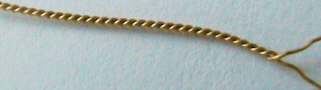
Closed in the ring
conductors, we replace the two tightly twisted conductors in the enamel
insulation (Photo 8). Let's pay attention that on a photo the left twist of
wires. Experiments have shown it matters. Probably, the similarity of the
"Lisažu Figures" is more likely to be
formed in such a twist than simply ring structures of DSS clusters. A
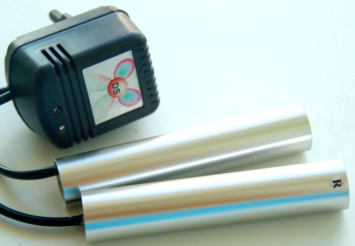
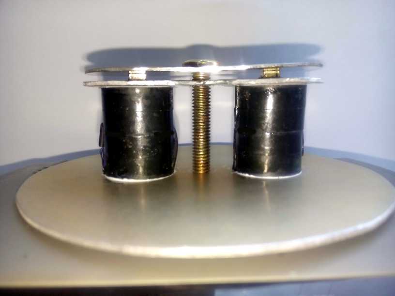
ready-made experimental device (Converter-R)
is on Photo 9. It is tuned to create comfortable sensations in humans. The
coils are inserted into two of its aluminum tubes. These coils are wound with a
double twisted wire (as in Photo 8), and are powered, as shown in Fig. 5. In
one tube there is a left twist of wires, in the other
is right.
|
|
|
|
Фото 8 |
Фото 9 |
As a result, a certain
analog of "prana" is produced-Yin and Yang. Or in other terminology -
clusters of DSS matter with predominantly left and right polarizations.
Naturally, we have an idea: we intend to use the three-stroke mode for the
variant shown in Fig.5. We add the alternating voltage (green sinusoid in Fig.7)
to the constant voltage between the conductors 4 and 5, and the electromotive
force of the self-inductance (the red sinusoid in Fig. 7) shifted in phase by
90 degrees.
|
|
|
|
|
|
Фото 10 |
Рис. 7 |
Рис.8 |
Рис.9 |
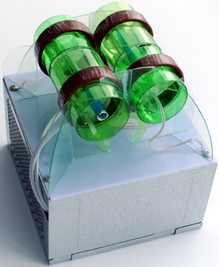
This option is
implemented in the Converter-U
(see Photo 10). Its electrical circuit is in Fig.8. Layout is in Fig.9. The
generated "axion field" is shown by the blue lines in Fig. 9. If we
look at Photo 10, the toroid of the "axion field" is formed around
the device.
Three-stroke operation
mode of the device can be represented as follows:
1.) Splitting into components
with pseudo-positive and pseudo-negative charges occurs in an electric field of
high intensity in DSS elements. As
an analog it is the separation of two wire springs.
2.) Components with
pseudo-positive and pseudo-negative charges undergo different external
influences. As an analog: one spring is stretched, the other is compressed.
3.) We remove the effect of an
electric field of high voltage. Components with pseudo-positive and
pseudo-negative charges approach each other due to internal forces of
attraction. Changes in individual components change into internal qualities of
DSS elements. (In particular, in the change in the spectrum of the eigenenergy
levels.) As an analog: two springs are pinched into each other and then we
remove the external effect. Redistribution of internal stresses occurs already
in a new configuration.
We can optionally change the ratio of the
change in the internal energy of the pseudo-positive and pseudo-negative field
components by combining the magnitude and direction of the electric current in
the wires (see Fig. 5) and the sign of the phase shift of the electromotive
force of self-induction with respect to alternating voltage between the
conductors. An increase in the pseudo-negative component, in theory, should
give a "tightening" effect, an increase in the density of the
"axion field," and a decrease in its "spreading" in space.
Perhaps a similar design
can be tried and applied to the transfer of ordinary matter in DSS matter.
Translation of Irine Lis