Alexander A.Shpilman ( alexandrshpilman78@gmail.com )
The Theory and Projects of
Measuring of the "Axion Field"
It is possible to assume that the
dominant factor in of the "axion field" in
a beam A of the generator G is the quantum-mechanical wave of a
proton, because the blanking of a beam occurs at a positive voltage
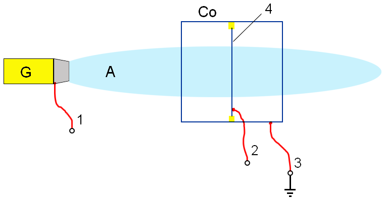
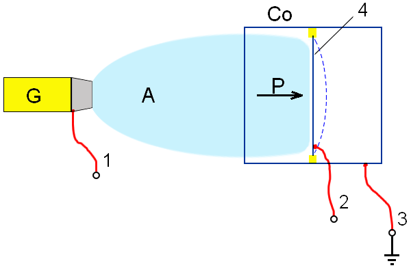
(approximately at 600-1500V - experimental observations) on an electrode 4 (see
Fig.1 and Fig.2).
|
Fig.1 |
|
|
Fig.2 |
|
But the beam of the
"axion field" is neutral electrically. It
also does not create magnetic field in macro-scale. It is possible to assume
that the "axion field" is the total of
quantum-mechanical waves of quarks of a proton with the charge +2/3 and -1/3,
and also quantum-mechanical waves of electrons. The macroscopic total of
electrical and magnetic fields is close to zero.
As quarks and electrons have
different coefficient of the ratio of a specific charge to their specific mass
(e/m) it is necessary to expect
dominant influence of the quark +2/3 in kinetic processes in electric fields.
It is necessary to
underline nonapplicability of the usual description
of a wave function of a proton to the description of a wave function of quarks.
Let's assume that the quark has his own frequency:
f = mq*c2/h
|
where |
mq Ц is a mass of a quark
in the proton; |
The wave length of a quark is
equal:
λ
= c/f = h/(mq*c)
We shall assume that we have two
quarks with f1 and f2 with opposition directional
propagation of a wave.
When a proton is
immobile f1= f2=f0 , we have zero beats and the wave length
of a proton is equal to infinity.
When the proton moves with velocity
V, the frequency of beats of a
standing wave will be:
fb = f1-f2
= γ*f0-f0/γ = γ*f0*V2/c2
where: γ = 1/(1- V2/c2)0.5
For small V the wave length of a proton will
be equal:
λ = V/fb
= h/(m*V)
|
where |
m Ц is a mass of a proton |
It coincides with the classical
formula of a wave length of a proton. Therefore it is possible to try to use
the accepted guess.
At electrical potential ~1-10V it is
possible to expect spatial deducted of a quantum-mechanical wave of an electron
from a beam of the "axion field". At
electrical potential ~100-180V (experimental observations) there is a spatial
partitioning of quantum-mechanical waves of quarks with opposite charges. In
the result in a neighbourhood of electrode 2 it is possible to expect display of inhomogeneity of an electric field and change of a
capacitance of electrode 2
relatively to a shielding box Co
(see Fig.1 and Fig.2).
Probably, the spatial partitioning
of quantum-mechanical waves of quarks with opposite charges is caused by
relative phase shift of their wave functions. Therefore not only electrical
potential is important (100-180V), but also the path traveled by a quantum-mechanical
wave is important at this potential too. The phase shift:
df ~ P(x)*dx= (P0- (q*U(x)* mq)0.5 Ц q*A(x)/c)*dx
|
where |
P0 Ц is an initial impulse of an quarks; |
It is possible to assume, that the
specific kinetic energy of unity of mass of the "axion
field" in a beam is equal:
w=U*e/m=U*k
|
where |
U - is an value of a
disabling voltage on an electrode; e - is an charge of
a proton; m - is an mass of a
proton; k= e/m |
Specific
impulse of unity of mass of the "axion
field" or its velocity is equal:
p=V=SQRT(2*U*k)
The
pressure on an electrode 2 is equal:
P=2*q*U=2*ρ*k*U
|
where |
ρ - is specific density
of mass of the "axion field"; q - is specific density of electrical charges of the "axion field". |
Thus, using an expedient of
measuring of pressure of the "axion field"
on electrode 2, it is possible to determine longitudinal moment of an impulse
and mass density of the "axion field".
From
the experiment concerning the action of the "axion field" on a torsion pendulum it is possible
to assume that the expected pressure on a membrane is 10-7 Pascal, and density of
the "axion field" is approximately equal to
10-18 kg/m3.
After spatial
partitioning of quantum-mechanical waves of quarks with opposite charges, it is
possible to partition them on a direction of a magnetic moment in a magnetic
field by intensity of 50
amperes/meters (more strong magnetic field becomes
strong garbles of a quantum-mechanical wave of a quark). If we previously
determine a mass density of the "axion
field", we can measure the magnetic moment of quarks.
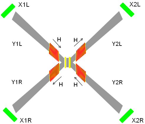
For realization of such measuring we offer the
construction shown in a Fig.3, 4, 5.
If
to assume that a mass density of the "axion
field" is 10-18 kg/m3 †and is electromagnetic in basic, we can
calculate an upper limit of expected quantity of a magnetic field:
H = (ρ*c2/μ) ~ 100 A/m
where: μ - is a magnetic permeability of vacuum.
The Description of a Design
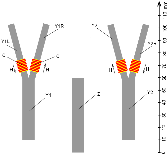
The design consists (see
Fig.3) in two lead plates Y1 and Y2 with thickness of 1 mm, having the
shape of letter Y. It also consists
of lead plate Z. The scale ruler is
shown sideways in Fig.3 and from the end of the face in Fig.5.
The dielectric bobbins C with the electrical coil are put onto
the plates Y1 and Y2. The coils are feeded
by an electrical current so the magnetic field H=50 ampere/meter inside the coils is directed as it is shown by
arrows in Fig.3, 4, 5.
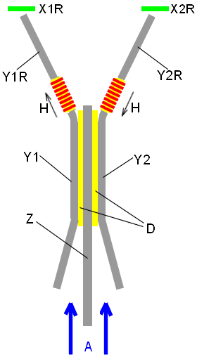
The plates Y1, Y2 and Z are incurvated
and are assembled in a pack, which is shown in Fig.4. The plates are separated
between themselves by the dielectric pellicle D, which has thickness of ~0.5 mm.
Between branches (Y1R, Y2R, Y1L, Y2L) of
plates Y1 and Y2 there are four sensing detectors of a magnetic field X1R, X2R, X1L, X2L (see Fig.4, 5).
The plate Y1 is connected to a voltage +180-250V.
The plate Z is connected to a voltage 0V.
The
plate Y2 is connected to a voltage
-180-250V.
Principle of Functioning
The "axion
field" has a direction shown by the arrow A. The "axion field" penetrates
into the lead plates Y1, Y2 and Z. The electrical potential between the plates separates the "axion field" components with a different electrical
pseudo-charge. The component with a negative pseudo-charge is spreading along
the positive plate Y1, and the
component with a positive pseudo-charge is spreading along the negative plate Y2. Then the "axion
field" components are separated by the magnetic field H of electrical reels C
along the different branches of plates Y.
The
separated components of the "axion field"
leave the ends of plates Y through the magnetic detectors X1R, X2R, X1L, X2L. At the odds of a voltage between
the plates Y1 and Y2 there are more than 360 volts (experimental
observations) going away from their branches beams of
the "axion field". They are not made among
themselves, therefore probably independent measuring of a magnetic field of
four "axion field" components having
different "electrical charge" and magnet moment.
See Separation Axion
(Spin) Field
and Physical properties of axion
(spin) fields
|
Fig.1 |
Fig.2 |
|
|
Fig.3 |
