Alexandr A.Shpilman (alexandrshpilman78@gmail.com )
EM "axion field" detector
(Idea)
Let us take as a basis the effect of
the magnetic vector potential on the "axion field". (we will use the assumed inductive ability of the field of
type 3. (See "Physical properties
of axion fields")
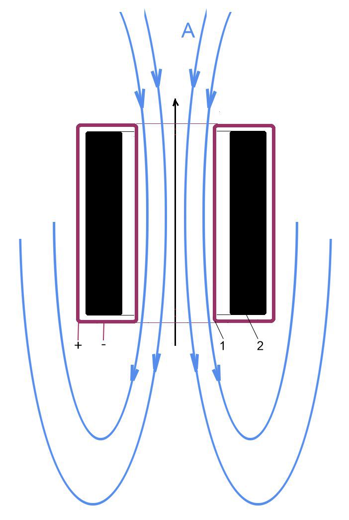
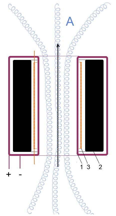
Consider Fig.1. For a toroidal coil
1 with a ferrite core 2, the "axion field flux" A (from an
external source) can be represented as the secondary winding of a transformer.
So, according to the change in the inductive characteristics of the toroidal
coil, in theory, it is possible to track the change in some characteristics of
the flow of the "axion field" A. But the problem is that the
"axion field" A induces an induced "axion field" in
the material of the ferrite core 2 and in the electrical wire of the
toroidal winding 1. Which will mask the external field A. There
are also possible problems of instability of the characteristics of the ferrite
core.
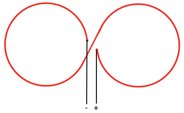
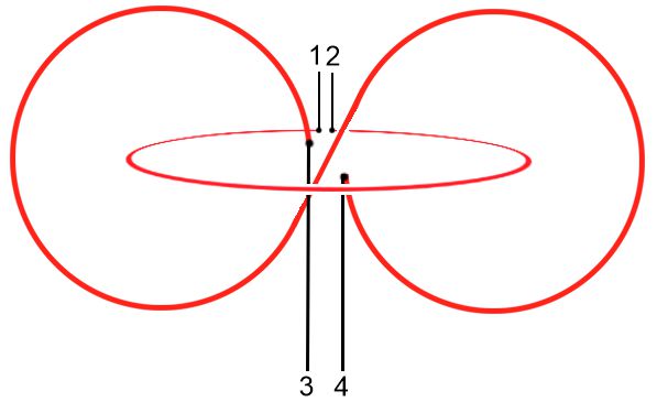
Therefore, we remove the ferrite
core and replace the toroidal coil with two turns of an electric wire twisted
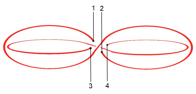
into a figure eight as shown in Fig.2. If we add another such figure eight,
rotated relative to the first by 90 degrees (Fig.3), then by changing the
currents in these coils, we can get the rotation of the direction of the
magnetic vector potential created by these coils. A change in the direction of
the magnetic vector potential will cause a change in the "axion
field" A flux penetrating the structure, which, in theory, can
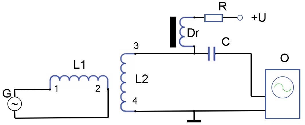
cause induction EMF in the turns of electrical conductors. Fig.4 shows a
variant of measuring this EMF.
Generator G generates alternating
current in the figure-of-eight L1. From the second "eight" L2
a signal, is measured on the device O. Constant magnetization in the
second "eight" L2 is set from a voltage source U
through a resistor R and a choke Dr.
|
|
|
|
|
|
Fig.1 |
Fig.2 |
Fig.3 |
Fig.4 |
The construction of Fig.3 resembles
Photo 1 of a key fragment of the images of "weapons of the gods" as
they are called in India.
|
|
|
|
Photo 1 |
|

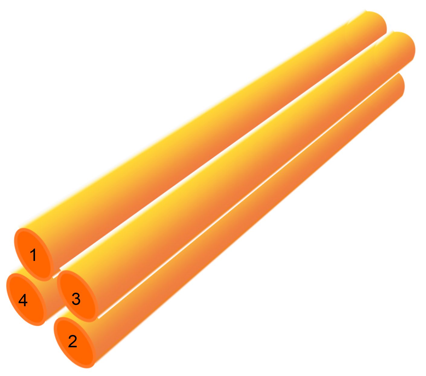
The structure Fig.3 can be transformed into a
long four-core electrical cord Fig.5. The disadvantage of the design will be
the large electrical capacitance between the veins of such a cord. And to
reduce the influence of the induced "axion field" in the material of
the conductors, it may be necessary to replace copper and silver with some
other metals or / and use thin conductors with a large gap between them. It is
also necessary to take into account the influence of dielectric materials in
the coating of the conductors. For example, celluloid and silk can be used as
insulation.
"Axion field" has such a
property as chirality (left and right polarization). Using this property, one
can try to modulate the "axion field flux" by changing the chirality
of the magnetic vector potential. To do this, add a cylindrical electric coil 3
to the structure shown in Fig.1, as shown in Fig.6. For measurement, you can
use the circuit shown in Fig.4, where L1 is coil 3, L2 is
respectively toroidal coil 1.
And the design shown in Fig.3 can be
converted to the design shown in Fig.7.
|
|
|
|
Fig.6 |
Fig.7 |
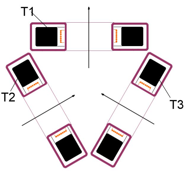
Subsequent development of the idea -
three toroidal coils T1, T2 and T3 are located as shown in
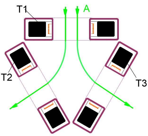
Fig.8. The current in the toroidal windings is set so that the magnetic vector
potential A is oriented as shown in Fig.9. The orientation and absolute
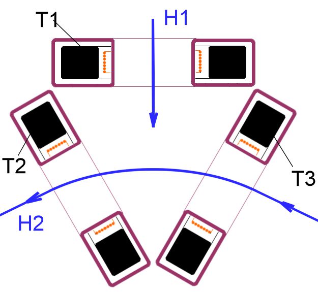
value of the magnetic field H1, which is created by the cylindrical
winding in the coil T1, is adjusted to the required chirality of the
measured "axion field" (see Fig.10). The same principle sets the
current in the cylindrical windings of the coils T2 and T3 (see
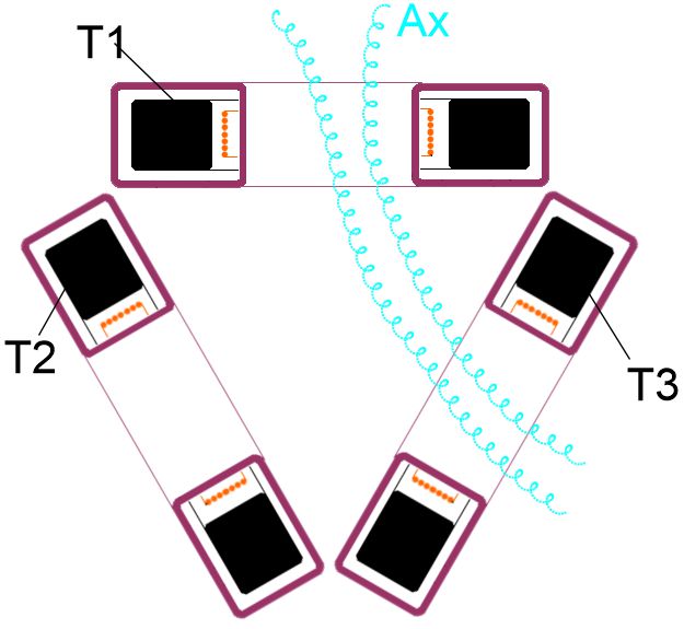
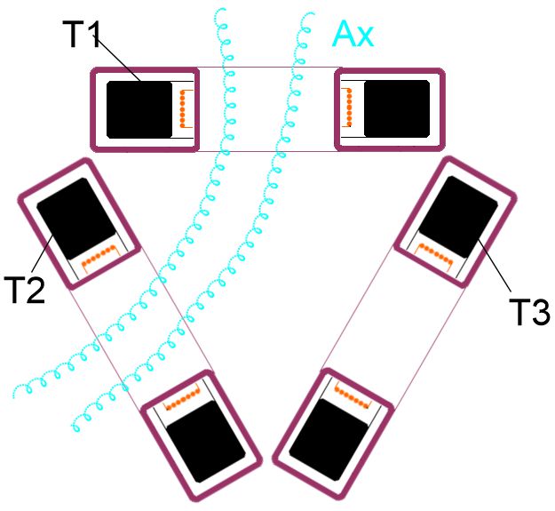
Fig.10). By switching the direction of the magnetic field H2, it is possible
to obtain the switching of the "axion field flux" Ax between
the coils T2 and T3 (see Fig.11, Fig.12). Which should cause the
induced EMF to appear in the toroidal windings of the coils T2 and T3.
|
|
|
|
|
|
|
Fig.8 |
Fig.9 |
Fig.10 |
Fig.11 |
Fig.12 |
From
the author: ideas are outlined here. Real designs will probably look a little
differently. For example, the designs shown in Fig. 3 and Fig. 7 can be made in
the form of braided braids or woven fabric.