Alexander
A.Shpilman ( alexandrshpilman78@gmail.com )
Measurement of The Longitudinal Moment of a Pulse "axion (spin) fields"
(The Project)
It is known from the experiment
that it is possible to fence SF such as 1
and 3 (see Physical properties of axion (spin) fields) by positive electrical
potential which is equal:
Up=P2/(e*m)
|
where |
m –
mass of a
proton e – electrical charge of a
proton P –
longitudinal
moment of a pulse SF |
The circuit of such an experiment is
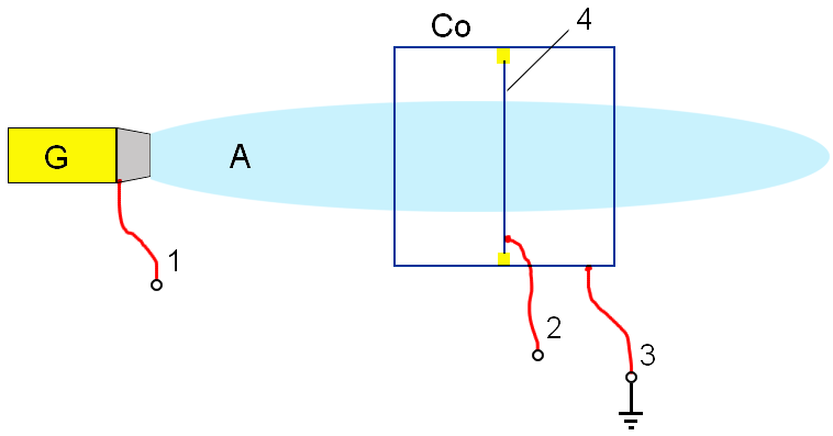
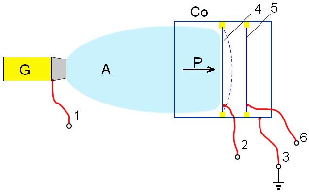
shown in Fig.1. Where the beam A of the generator G penetrates a box Co and membrane 4
of a thin aluminium foil.
|
Fig.1 |
On contact 2 of membranes 4
feed high positive electrical potential (600-1500V) relatively contact 3
boxes Co and contact 1 of the body of the generator G.
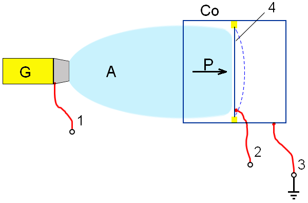
Thus the propagation of the beam A of the generator G is limited
as it is shown on Fig.2.
|
Fig.2 |
It is supposed, that the beam A
limited by such a method, should pressure on the membrane 4. It can
cause a change of electrical properties and mechanical deformation of the
membrane 4.
It
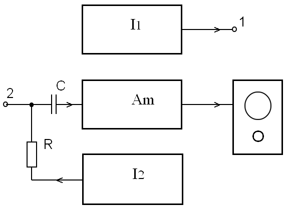
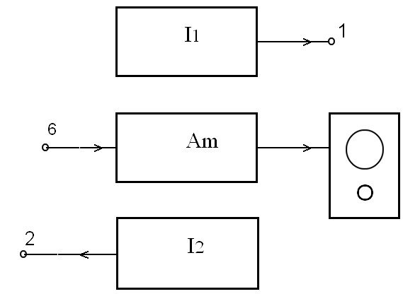
is offered to use the electrical block the circuit shown on Fig.3 for detection
of a change of electrical properties of the membrane 4.
|
Fig.3 |
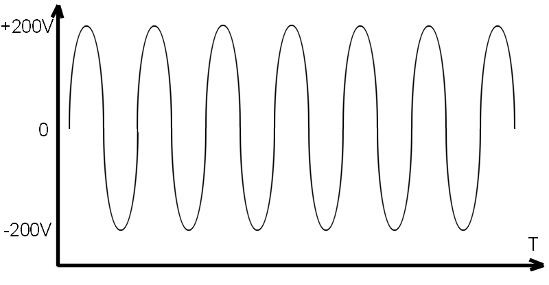
The voltage from the
source I1 of a variable voltage by amplitude 50-200V and frequency ~1
KHz (see Fig.4), through the contact 1 (Fig.1,2,3) moves on the body of
the generator G (Fig.1,2) for modulation of the beam A. The
sawtooth voltage 500-1500V from the source I2 with frequency ~1-10 Hz
(see Fig.5), through the resistor R contact 2 (Fig.1,2,3) moves
on the membrane 4 (Fig.1,2). Variable voltage by the induced beam A
on the membrane 4, through the contact 2 (Fig.1,2,3) and
condenser C moves on an input of the amplifier Am. Then the amplified
signal moves on an oscillograph O.
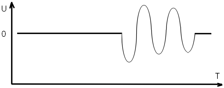
It is supposed that we
shall observe a signal shown on Fig.6 at achievement of a voltage on a membrane
of 4 some threshold voltages Up on an oscillograph O.
The presence of a threshold voltage Up allows to distinguish and
intercept noises. The introduction of synchronous detection of a signal with
frequency of modulation of the beam A can help to increase the relation
signal/noise and will raise sensitivity of measurings.
|
Fig.4 |
|
Fig.5 |
|
Fig.6 |
The signal shown on Fig.6 can be a
consequence of electrical processes on the membrane 4, but can be also
consequence of change of a capacitance of the a membrane 4 relatively
the electrical screening box Co because of mechanical deformation of the
membrane 4 (see Fig.2).
The
effect of mechanical deformation (a sag) can also be used for the membrane 4
for measuring a longitudinal moment of an impulse of the beam A. For
this purpose it is possible to measure changes of an odds of air’s pressure
between left and right volume of the box
It
is possible to add an additional membrane 5 for measuring change of a
capacitance between the membrane 4 and the membrane 5 at
deformation of the membrane 4. Actually, it will be a capacitive
microphone.
The electrical block circuit of
connection of such a capacitive microphone is shown on Fig.8. The sawtooth
voltage (Fig.5) from the source I2 through the contact 2
(Fig.7,8) moves on the membrane 4. The membrane 5 through the
contact 6 is immediately connected to the amplifier Am. It is
expected to get the signal on an oscillograph similar shown on Fig.6.
|
Fig.7 |
|
Fig.8 |
Probably, it is possible
to try to use a usual capacitive microphone (after some updating). And
probably it is possible to register "tinnitus " of our aura. That
tinnitus in ears, which we hear in silence.
