|
|
You can buy the generator of the
described design Attention, this generator is not a
magic wand! Its main destination - to carry
out of researches. (Information on E-mail: alexandrshpilman78@gmail.com ) |
Alexander A.Shpilman ( alexandrshpilman78@gmail.com )
The Generator of
"Axion (Spin) Field"
"COMFORT-M5"
(continuation,
beginning in N1/01)
The
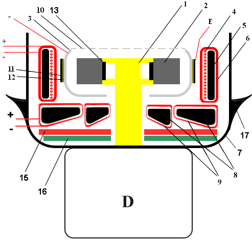
generator COMFORT - M has not only axial and radial components of an "axion field", but it also has an azimuth component.
That is why there is a sense to form not
condensers on the perimeter of the reflector 3 made which are closed in a ring,
but to form the condenser in a form of an oblique comb as it is shown in a
Fig.2. Where an interior plate is the reflector 3; an exterior plate is a
graphite coat 11 and celluloid films 12 (see Fig.1).
|
|
|
|
Fig.1 |
Fig.2 |
The
generator with the described construction has already been given a new name
- COMFORT - 7.
The Principle Electrical Circuit
It is naturally that the generator also
has electronic construction. I am describing here the principle electrical
circuit of the generator COMFORT for the first time.
|
Fig.3 |

C1 -
2000mF, 16V
C2 - 470mF,
16V
C3, C7, C8, C10 –
0.1-0.22mF , ceramic capacitor;
C4 - 4700pF ,
sets repetition frequency of packages of high-frequency pulses;
C5*, C6* -
10-30pF,sets porousness of work of a high-frequency switch DD3 and high frequency;
C9 – 5/25
pF tuning capacitor (Adjustment
of frequency of generation - 4.3-4.8 MHz);
C10 - 2700 pF, 150V; C11 - >1000 pF, 200V;
D - the electric motor RF-310T-11400;
DD1 -
LM555CN-8 (KP1006BИ1);
DD2 -
SN74ALS123N (K1533AГ3);
DD3 -
SN75452N (K155ЛА18);
L1 - the toroidal
coil 9 (Fig.1);
L2 - the toroidal
coil 6 (Fig.1);
L3 - the coil 4 (Fig.1);
T2 - The high-frequency
transformer. Amplitude
output voltage 100-120V at frequency 4.3-4.8 MHz.
R1, R2, -
100-220Ohm - the multiturnaround tuning resistor;
|
R3 - 24 kOhm; R4 - 18 kOhm; R5 - 22 kOhm; R6 – 5.6 kOhm R7 – 2.7 kOhm |
R8 – 4.7 kOhm; R9 - 10
Ohm; R10 - 220
kOhm; R11 - 1.5
kOhm. R12 - 1 MOhm |
V4,..., V10 - the
silicon semi-conductor diode;
V2 -
mA7805T (KP142EH5A) - the
stabilizer of voltage 5V;
V3 -
ES7809P (KP142EH8A) - the
stabilizer of voltage 9V.
Connect point A
to contact 16 of microcircuits DD2 and to contact 8 of microcircuits DD3.
Connect point B
to contact 8 of microcircuits DD2 and to contact 4 of microcircuits DD3.
Connect point C
to reflector 3 (Fig.1);
Connect point E
to contact E (Fig.1 and Fig.2).
|
|
You can buy the generator of the
described design Attention, this generator is not a
magic wand! Its main destination - to carry
out of researches. (Information on E-mail: alexandrshpilman78@gmail.com ) |


