Alexandr A.Shpilman (alexandrshpilman78@gmail.com )
"Axion
field" in electromagnetic fields
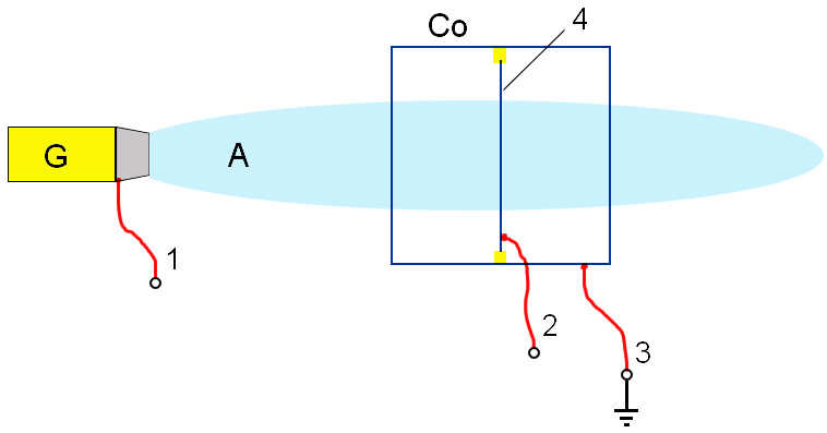
The "Axion
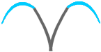
field" of radiators is described in the Introduction. It is displaced from
the region of space with a strong magnetic field and with a larger positive
electric potential with respect to the emitter, as shown in Fig.1,2.
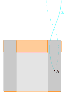
The ray A
of the generator G pierces the Co box and the membrane 4 from a thin aluminum foil.
|
|
|
Fig.1 |
|
|
|
Fig.2 |
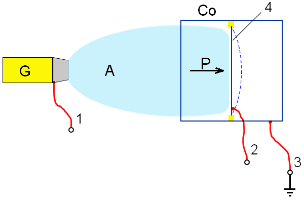
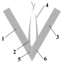
A high positive electric potential (+
600-1500V) is applied to the contact 2 of
the membrane 4 relative to the
contact 3 of the box Co and the
contact 1 of the housing of the
generator G. In this case, the
propagation of the ray A of the
generator G is limited as shown in
Fig.2.
It is possible to
estimate the longitudinal pulse in the ray AF of the generator G from the value
of the blocking voltage on the membrane 2, and it is possible to calculate the
mass of the AF ray from the pressure on the membrane 4.
This experiment confirms that the lead in the beam of the AF generator is a component with a
positive electric charge. This circumstance, in the general case, makes it
possible to use electret films with large positive electric charge for shield
the axion field. (This is verified on screening of "geo-fields".)
This
experiment naturally poses the problem of separating the components of the AF
ray from the sign of the electric charge. The experimental device is
schematically shown in Fig.1. The electrodes 3 and 4 are made of a
set of lead plates. They are bragging in the region 5 an electric capacitor with a solid dielectric (for example, from
a celluloid film). The AF - 2 ray is
directed to the end of the capacitor 5
from the generator 1. A positive
voltage is applied to the electrode 3, and a negative voltage is applied to the
electrode 4.
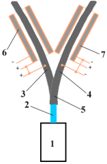
Fig.3
Lead in this design with respect to the AF
field performs a role similar to that of optical quartz fiber (optical fiber)
for light. Toroidal coils with an iron core 6 and 7 prevent
premature release of AF components through the side surfaces of lead electrodes
3 and 4.
|
|
|
|
|
|
|


When the voltage is zero between the stacks of
plates 3 and 4, the two AF rays at the output of the device are
"attracted" and go a long distance, oscillate relative to the average
position and generally curl into a spiral (Fig.4).
The voltage difference between electrodes 3 and 4 of ~ 20 volts causes what resembles (counter) "closure"
of the AF (Fig.5). Apparently, this is the moment when the separation of AF
into fractions begins in an electric field.
Places of concentration of AF intensity appear
in the space surrounding the device. They resemble volumetric interference
fringes of complex shape. These bands greatly impede further observations,
continuously changing their shape and size with a further increase in the
stress difference.
This may mean that the components of the AF change their internal energy differently when
divided into fractions.
"Arc" AF "sags" when the
voltage is increased to 180 volts (see Fig.6) and closes almost directly at a
voltage of 190 volts (Fig.7). It should be noted that the components of the AF
ray turn out to be closed oppositely with respect to the original motion in the
ray at the point of closure of the AF along a straight line.
If the voltage is increased to 260-300 volts,
striations appear and their clarity increases (the "arcs" of
interference fringes are continuously lowered). Then there is a sharp break in
the closing of the rays, and two divergent rays clearly appear (see Fig.8).
An increase in repulsion between the rays
causes a further increase of voltage, their bending. The beams are closed to an
AF source at a voltage of ~ 600 volts (Fig.9).
This may mean that the interaction between the components of AF is, in many respects,
resonant.
Naturally, the figures for the voltage
difference at the electrodes are relative. They depend heavily on the materials
used and the design of the instrument, and also depend strongly on the source
of the AF.
|
|
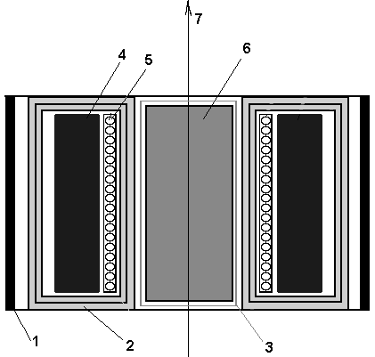
The device is made to find out how the AF
components interact with their own. This device shown in Fig.10. It is made of
a V-shaped lead plate with 1,3 arms.
The lead plates 2 and 4 are attached to the plate. The plate 2 forms a capacitor in the region 5 with the arm 1, and the plate 4 forms
a capacitor in the region 6 (on the
opposite side). Plates 2 and 4 are bent so that a semblance of a
four-sided pyramid is formed. The positive potential is fed to the V-shaped
plate, and the negative potential is applied to the plates 2 and 4.
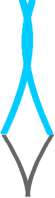
If the ray of the AF (as well as in Fig.3) is
directed to the tip of the pyramid, then we get four rays at the output of the
device at zero voltage. These rays interact with each other, as in Fig.4.
If the voltage (~ 20 volts) is sufficient, an
"arc" of AF is produced between the electrodes 1 - 2 and 3 - 4. The "arc" does not occur between the electrodes 2 - 3 and 1 - 4, even if we close their upper ends
almost closely.
This may mean that, although we have divided AF
into components by means of an electric field, but the interaction between the components of AF is not the interaction
of electric charges. We can imagine that the ray of AF consists of
individual fibers. When the splitting of the fiber components occurs in an
external electric field, there remains an indissoluble connection between these
components.
Why is the splitting observed in the
constructions shown in Fig.3,10 and is not observed explicitly in the
construction depicted in Fig.2? Probably, the
splitting is connected with the raid of the phase difference of the wave
functions of the AF components on the path of different branches of the
"fork" with different electric potential. As we know from quantum
mechanics, this phase difference foray is approximately equal to:
df~ SQRT(q/m *U(x))*dx
here q - is the specific pseudo-electric
charge of the AF component;
m – is the specific mass of the AF component;
U – is the electric potential
SQRT – is the square root.
The splitting of the components occurs due to the
longitudinal pulse of the ray AF. The kinetic energy goes into the potential
energy.
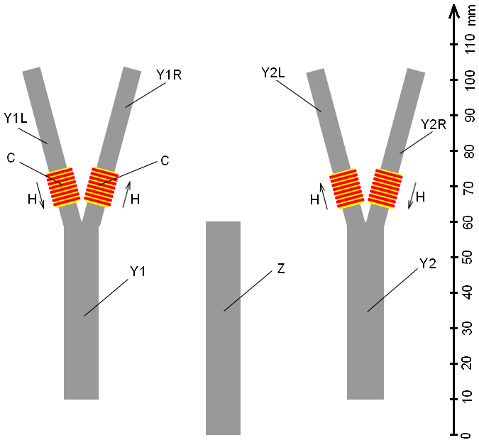
The
topic can be developed if we divide the
components of the AF ray also by the magnetic moment. The design for this
experiment consisted of (Fig.11) two lead plates Y1 and Y2 thick1 mm, having
the shape of the letter Y, and the lead plate Z. Figure 11 shows the scale
ruler.
Dielectric bobbins C with an electric coil were
put on plates Y1 and Y2. The current in the coils provided a magnetic field
strength H = 50 ampere / meter which was directed as indicated by the arrows in
Fig.11,12.
The plates Y1, Y2 and Z were bent and assembled
into a bag, as shown at the side in Fig.14 and from the end in Fig.The plates were separated between each other by a
dielectric spacer D, with a thickness of ~ 0.5 mm.
At the ends of the branches (Y1R, Y2R, Y1L,
Y2L) of the plates Y1 and Y2, four sensitive magnetic field detectors X1R, X2R,
X1L, X2L were supposed to be installed (see Fig.12,13).
The plate Y1 was connected to a voltage source
+ 180-250 V.
Plate Z had zero potential.
Plate Y2 was connected to a voltage source of
-180-250 V.
|
Fig.11 |
Fig.12 |
|
|
Fig.13 |
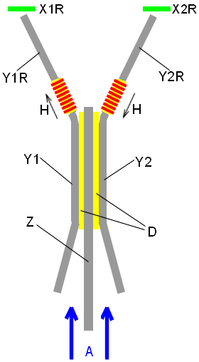
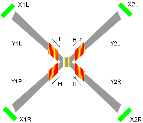
Four divergent rays were observed from the
branches of the plates Y1 and Y2 under the voltage difference between them. We could
suppose that the separation of the components of the ray AF was achieved
simultaneously with respect to the sign of the pseudo-charge and the magnetic
moment. But alas, we could not find enough sensitive magnetic field sensors.
We must verify the reaction of AF to the Poiting vector.
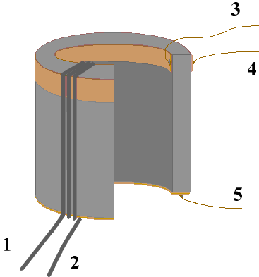
The AF
emitter (see Fig.14) was made for testing. It consists of a ferrite tube 4 with a height of 12 mm, with an outer
diameter of 9 mm and a wall thickness of 1 mm. The cylindrical electrodes 3 and 4 were pressed to the inner and outer surfaces of the tube.
Electrodes were supplied with an alternating voltage of 12v and a frequency of
the order of 3 MHz. The toroidal winding of three
turns was wound on the tube. We passed an alternating electric current in phase
with the electric voltage at the electrodes and an amplitude of 0.3 A through
the winding (conclusions 1,2).
|
|
|
|
Fig.14 |
Fig.15 |
Theoretically, the acceleration of dissimilar
pseudo-charges in one direction (in the direction of the Poiting
vector) in the walls of the ferrite tube along its axis was to occur in the
mutually orthogonal electric and magnetic field of the device. And AF has
arisen! Moreover, AF has appeared with a significantly higher field density
than many other variants of the construction of AF generators using mechanical
rotation or rotation of electromagnetic fields!
But, the ray of AF was formed in the opposite direction
to the direction of the Poynting vector!? In
other words, if you excite the AF with
light, the AF ray will be drawn to the light source. This means that, in part,
AF is a stream carrying something like an electric charge and moving from
outside to the generator (let's call it Z1) !?
An increase of the amplitude the electric
voltage oscillations at the electrodes beyond the optimum led to the appearance
of something along the ray AF, like the standing waves in a guitar string, with
a characteristic distance between the antinodes in the air of the order of
15-20 cm (Fig.15). This could mean that
the velocity of the flow of Z1 along the ray of the AF is of the order of 105 m
/ sec, and that either the reflection occurs somewhere with the appearance of the
backward wave, or there is a flux in the AF beam (neutral or with a much
smaller specific electric charge) moving
from the generator to the outside (we call it Z2) and it interacts strongly with the flow Z1.
The
shift of the phase of the change in the electric voltage at the electrodes and
the magnetic field in the ferrite tube led to a substantial increase in the
density of the generated AF beam. As a result, the phase of the change in the
electric potential at the electrodes 3,4 coincided with the phase of the
self-inductance of the toroidal coil. Apparently, the coincidence with the
phase of the self-induction of the toroidal coil is most effective at the
moment of maximum splitting of the AF beam according to the sign of the
pseudo-charges between the electrodes 3 and 4. (This point will be considered
in detail later.)
The
characteristic blocking electrical potential in the air reached + 1200-1500
volts for this generator (according to the scheme in Fig.1.2). Considering the
velocity of the flow Z1 along the ray AP of the order of 105m / sec,
we obtain the ratio of the charge
density to the specific mass of the flux Z1 (q/m) very close to the
corresponding value of the proton! (This is not "micro lepton",
but "microbesons"! ...). Elementary
calculation of the flow velocity with a blocking voltage of +1200 V gives the
speed:
V~ SQRT(2*q/m *U) = SQRT(2*9.6*107*1200)
= 4.8*105 m/s
The blocking voltage in the air of +1200 - 1500
V at an amplitude voltage of 12 V between the electrodes 3-4, and the self-induction
EMF of the toroidal coil of 15 V/coil, suggests that the impulse of motion of Z1 in the ferrite tube is two orders of
magnitude less than in air. Accordingly, the speed will be two orders of
magnitude smaller, i.e. about 103 m / sec.
We can conclude from this experiment (according
to the scheme in Fig.1.2), that the leading component of AF-Z1 has a
pseudo-positive charge. The same component is oriented to meeting the vector of
the Poiting. We conclude: Рис. It remains to assume that Z2 is a flow with a pseudo-negative charge
from the source to the outside.
These conclusions have been confirmed in other
designs of AF generators.
"Axion
field" is not a correct name, but it has been a basis. This is indicated by the experiment
with the construction of the "Electrodynamic generator" Axion field
", shown in Fig.1
|
|
|
|
Fig.1 |
Fig.2 |
Here 1
- iron tube; 2 - electric toroidal
winding of the ferrite core 4; 5 -
cylindrical electric coil of bias of active element 6 (for example, ferrite with small electrical conductivity); and 3 - a drum with vertical plates of
electrodes (see Fig.2) creating a rotating quadrupole electric field in the
active element 6 perpendicular to the axis 7.
Resonance of AF generation was observed in the
range 1-10 MHz.
In this design, the ray of the AF changed its
direction along the 7 axis when the frequency of the three-phase voltage changed
(it went up and down). This effect is reminiscent of "Nuclear Magnetic
Resonance" (NMR) and "Nuclear Quadrupole Resonance" (NQR). It is
probably possible to talk about the
presence of an analog of spin and the magnetic moment for the components of AF.
Translation of Irine Lis