Si-Chen Lee ( sclee@cc.ee.ntu.edu.tw )
Torsion Field
and Its Detection
Prof. Si-Chen Lee
Department of Electrical Engineering National Taiwan University
|
|
|
NMR spectra
|
B = 11.74 T, 500MHz
|
|
Results without TFG Illumination
|
|
|
Time relative to TFG illumination, t (min.) |

Green curve : No TFG
Orange curve : TFG through wetted paper
filter
Results after TFG Illumination for 3 minutes
Normal saline 17O NMR
after TFG illumination
|
|
|
Time relative to TFG illumination, t (min.) |
2 mm thick metal aluminum as blocking material (SN27)
No blocking Material (SN18)
|
|
|
Time relative to TFG illumination, t (min.) |
Stainless Steel (SS) as Blocking Material (SN26)
Metal Mo as Blocking Material (SN30)
Normal saline 17O NMR
after TFG illumination
|
|
|
Time relative to TFG illumination, t (min.) |
Torsion Field Does Exist
!
Its transmission properties
- Absorbed by water
- Unchanged through 2mm thick aluminum
- Negative peaks appear when penetrating
stainless steel and Mo
- Similar to those of crystalling
Qi
Direct Detection of Torsion
Field by using Exclusion Zone of Water
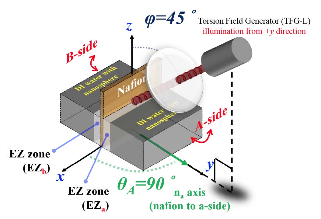
The TFG illumination setup must be described in details
Tilt
angle φof TFG to the vertical z axis; deflection angle θA of chamber A-face to the x axis
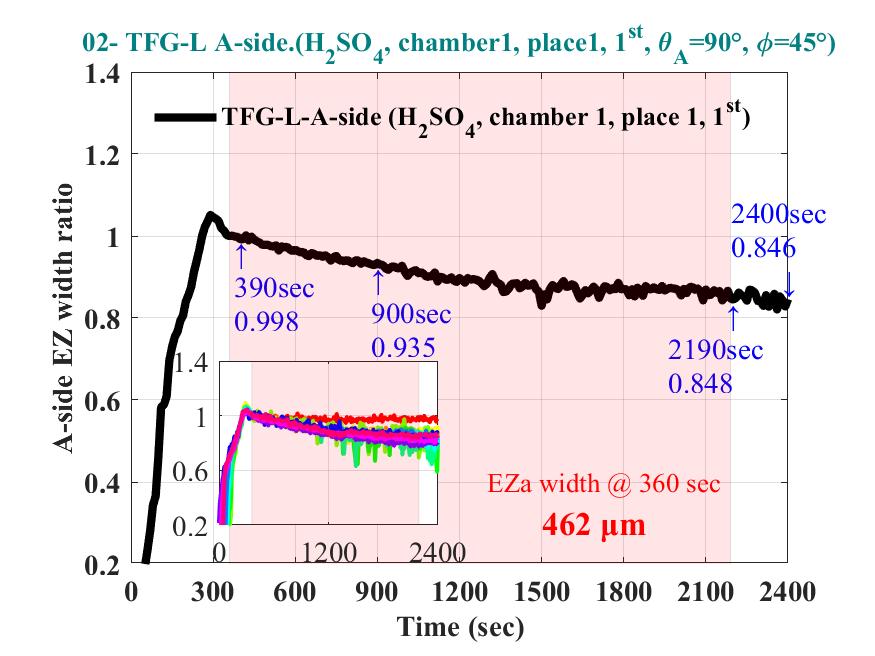
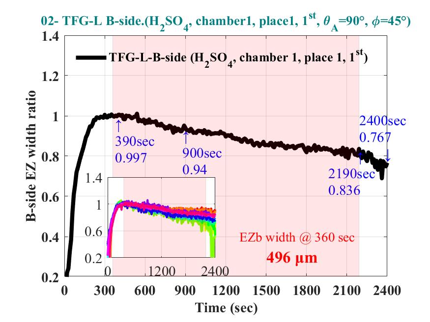
The EZ direction is along x axis
There are two Ezs at two
sides of the Nafion film
one facing the torsion field is defined to be A-side.
The other across the Nafion film is defined to be
B-side
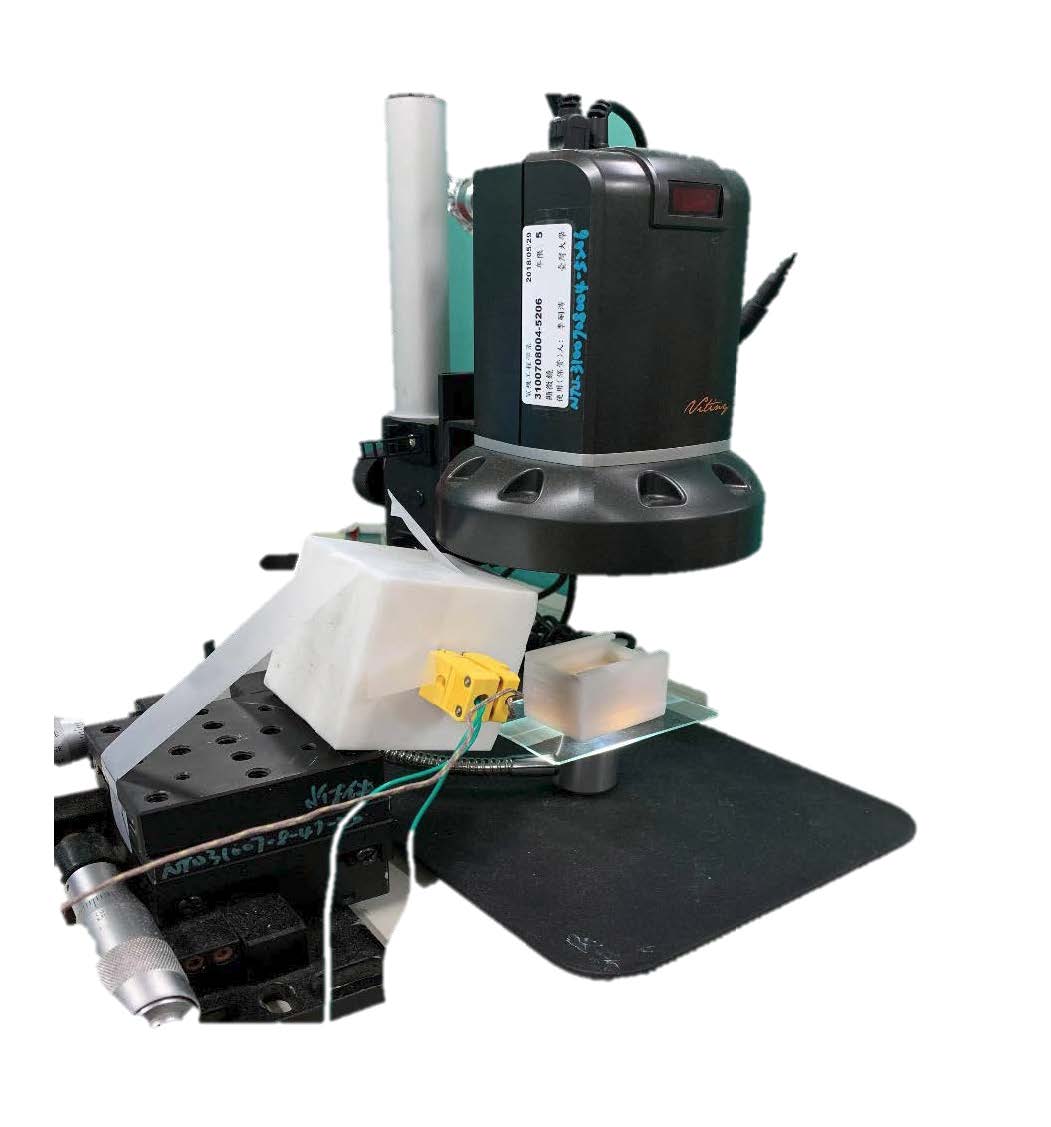
EZ zone Measurement Setup
|
|
|
|
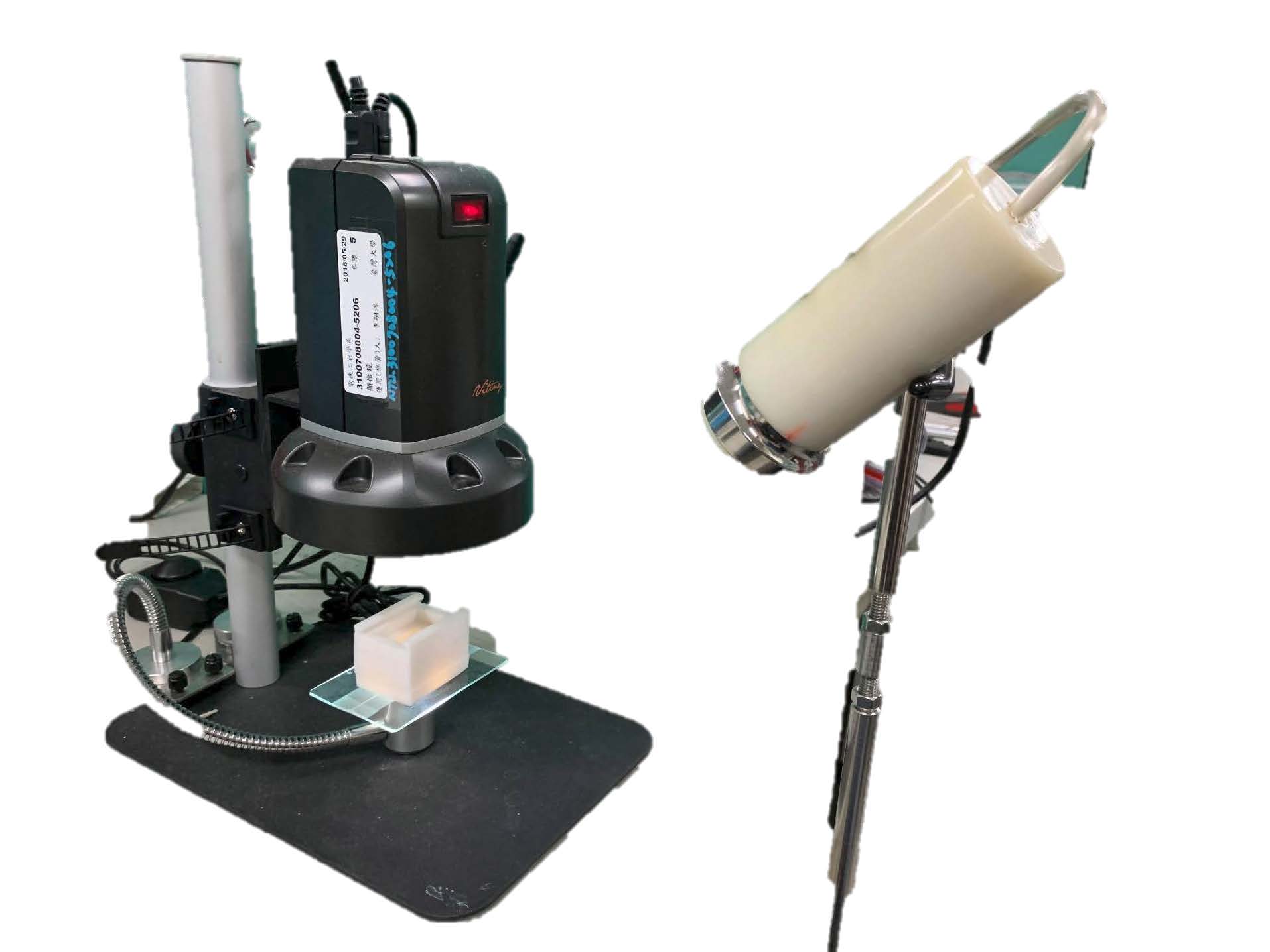
Preparation Procedures
1.
0.5 * 2.0 cm2 Nafion-117 cleaned by solution (30min,
at RT).
2.
Nafion installed in a white Teflon
chamber .
3.
0.5 wt % nanoparticle (500nm –COOH- modified
PS spheres was injected.)
4.
Sealed by glass to eliminate environmental disturbance.
5.
Observed by OM with light coming from bottom of chamber.
6.
L-TFG was set and illuminated toward negative y-axis.
7.
EZ pictures was recorded every 10 sec automatically by PC.
|
|
|
|
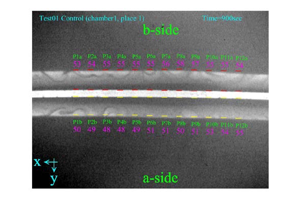
Time 900 sec
|
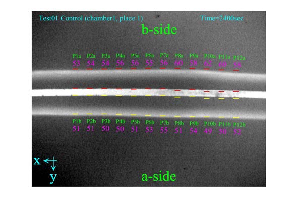
Time 2400 sec
|
Quality of EZ using different cleaning solutions for Nafion
film
Three cleaning solutions :
−
WATER
−
H2SO4
−
ACETONE
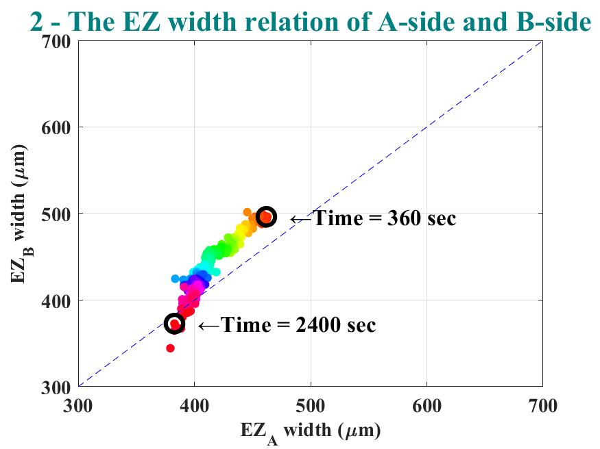
• Quality is judged by the asymmetry
between A &B-side EZ widths
***
The quality of Nafion
surface
(EZ width difference between A and B-Side)
|
|
|
|
(EZa – Ezb) |
(EZa – Ezb) |
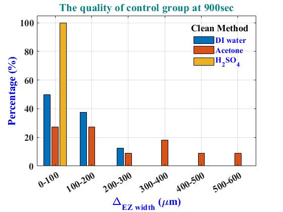
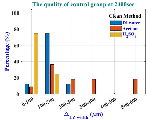
Water is good but 1% H2SO4is better
***
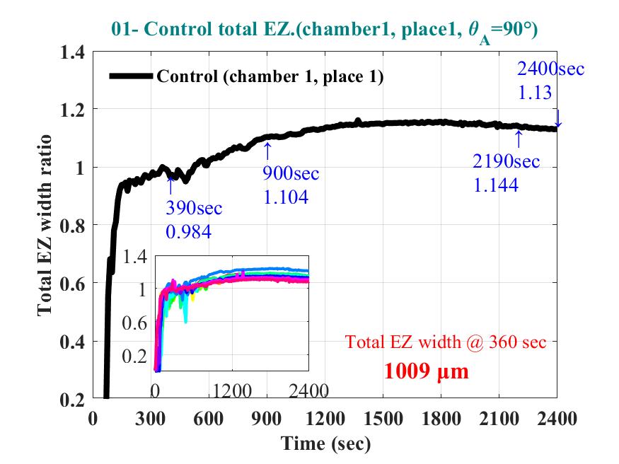
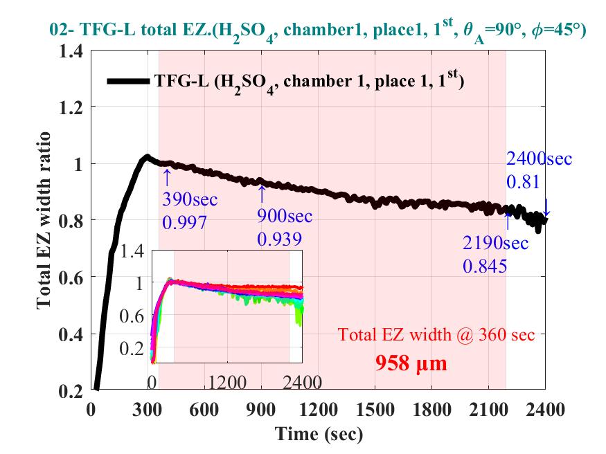
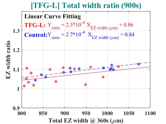
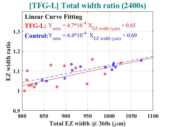
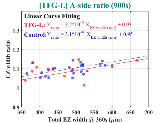
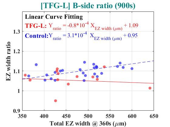
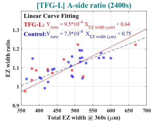
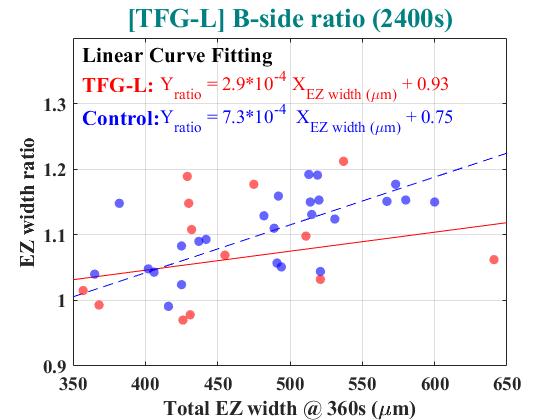
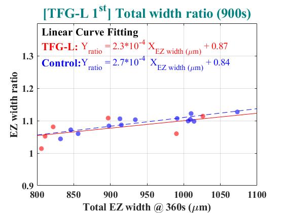
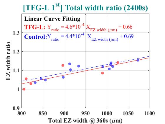
Total or single-side EZ width ratio of control
experiments as a function of original total or single-side EZ width
Nafionfilm
117 cleand by water
0.5% –COOH–modified
PS nanosphere (500 nm)
Measured
at 900 and 2400 sec
|
|
|
|
|
|
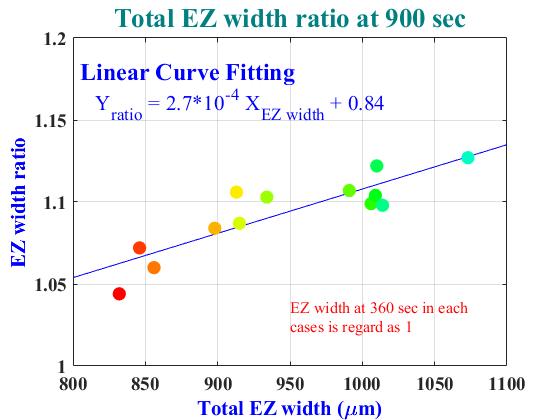
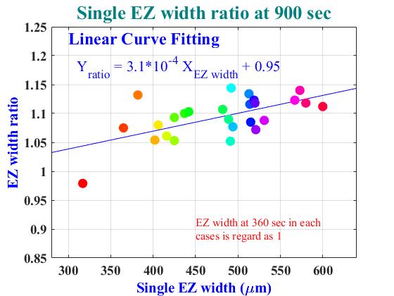
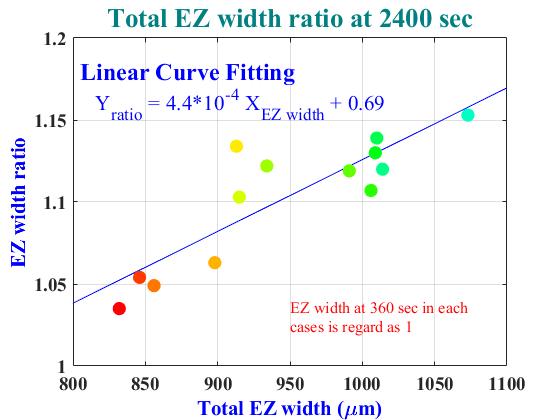
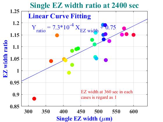
Criteria @ 360 sec:
•Total EZ width >= 800μm
•Single EZ width >= 350μm
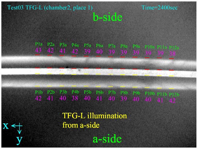
Pictures of A &B side EZ after TFG-L illumination
for 30 mins
|
|
|
|
|
|
|
|
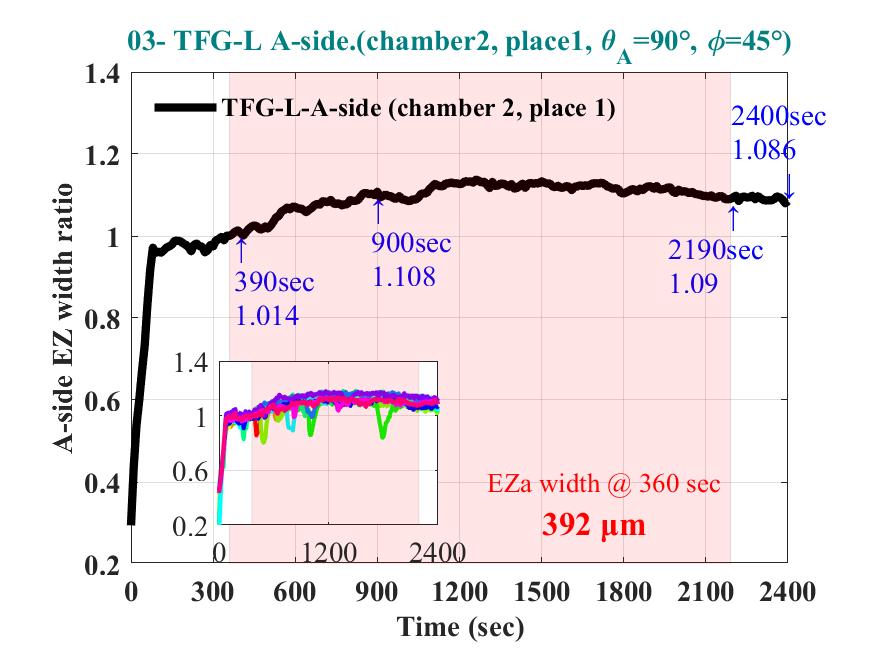
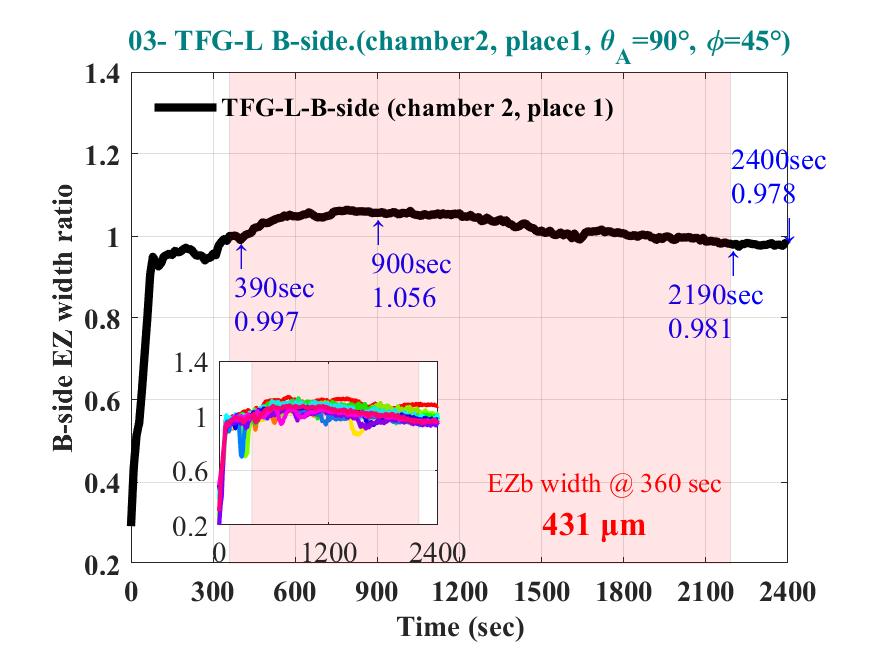
Two different build up
mechanisms of EZ zone results in opposite behavior after TFG illumination
The EZ width build up process with different diluted solution.
|
|
|
The Effect of TFG
Illumination on EZ Width
(Nafion117, 0.1% 200 nm –COO-modified PS sphere)
|
|
|
|
|
|
Total EZ
width ratio at 900&2400 sec All used 500 nm PS spheres
|
|
|
(The EZ width at 360 sec in each
case regard as 1)
***
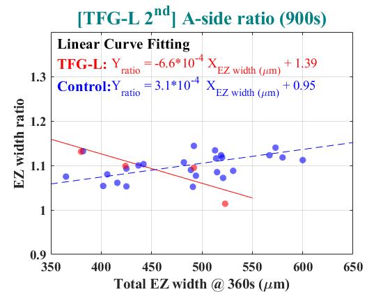
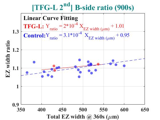
Residual Effect Of Torsion Field
Study the effect of TFG illumination on
the chamber
Same chamber was used for three times
New Nafionand solution were
used in each experiment
***
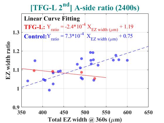
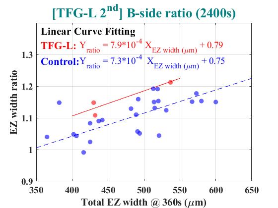
A&B-side EZ width ratio at 900 & 2400sec
|
A-side |
B-side |
|
|
|
|
|
|
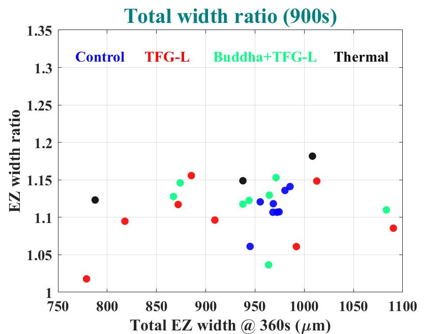
Total EZ width ratio at 900 &2400 sec
All used 500 nm PS spheres
|
|
|
(The EZ width at 360 sec in each
case regard as 1)
A &B-side EZ width ratio at 900 & 2400 sec
|
A-side |
B-side |
|
|
|
|
|
|
***
Nafioncleaned by 0.1% H2SO4
–COOH– modified PS nanosphere (500 nm)
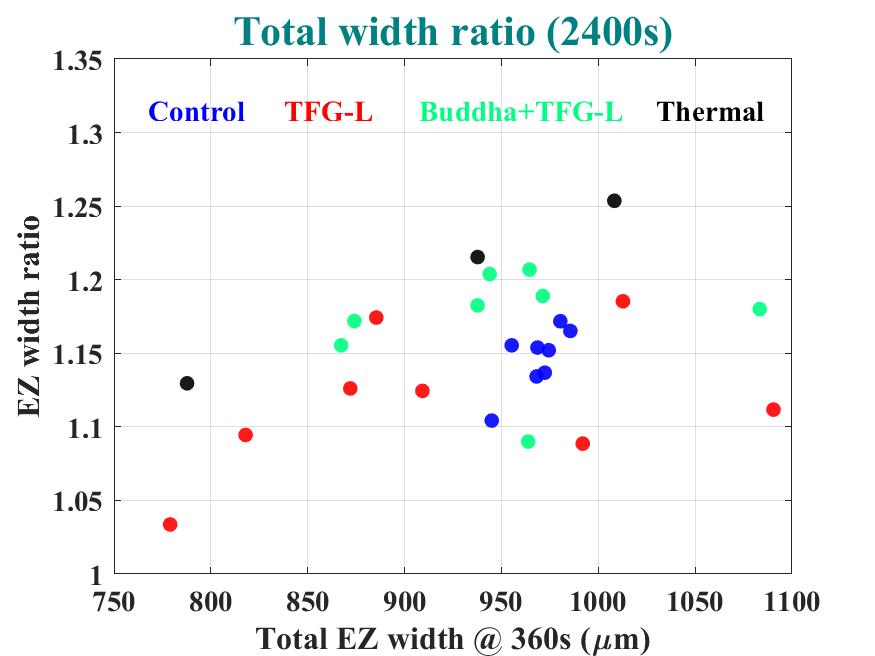
Illumination Conditions
– Control
– TFG-L for 30 mins
– TFG-L through “Buddha”
for 30 mins
– Infrared with 3.0 um
wavelength for30 mins
– Blackbody radiation at
250oC for 30mins
EZ zone (0.1% H2SO4cleaned)
Film type: Nafion117.
Solution:
500nm PS nanosphere.
–COOH–modified.
Concentration
= 0.5 wt%.
|
Item |
θa |
Blank |
Time
(sec) |
OM direction |
Experiment
times |
|||
|
|
1st |
2nd |
3th |
Total |
||||
|
Control |
90° |
Whitepaper |
2400 |
+ y |
|
|
|
8 |
|
TFG-L |
90° |
Whitepaper |
2400 |
+ y |
3 |
3 |
3 |
9 |
|
|
The effect of blackbody radiation 0r 3 um IR(at 250oC)
(Nafion 117, 0.5 % 500 nm–COO- modified PS sphere)
|
|
The EZ width ratio of different condition (900s,
2400s)
|
|
|
***
Conclusion
TFG illumination conditions on EZ and experimental
procedures have to be standadized