Gao Peng ( gpufo@outlook.com )
The Scalar Wave Technology Research Web in China The laboratory of Beijing Wellan Century Co., Ltd
Detection Of Torsion Field Based On Measuring The Dark Current Of
Silicon Photodiode
Abstract:
This work studies detection of torsion
field by way of measuring the dark current of silicon photodiode. For this
purpose, a photodiode which works in reverse bias state and a
ultra-weak current detector should be used in all the related experiments,
because the dark current of selected photodiode is in pA(10-12A) level.
According to the results,the
right-handed torsion field can make the dark current decrease and the left-
handed torsion field can make the dark current increase.
1. Introduction
In the third chapter of [1], Dr.S.Kernbach introduced many approaches for detecting torsion field or 'high-penetrating' emission. Author ever used the torsion balance approach consisting of a wooden frame to detect the torsion field nature of scalar wave generated by Tesla scalar system[2]. But there is no data recording in this approach.
Water is very sensitive to torsion field according to previous research works. So the water-based approaches, such as dpH[3][4], EDL[5][6],DTA[3], UV Spectrophotometer[1] and so on can be very sensitive. But maybe the rate of change in water-based system is a little small.
In some of the approaches according to [1], there are some solid-state approaches based on dielectrics, semiconductors,ferromagnetics,resistors, changes in some properties of electric fields and so on. In the book with the property of collection [7], the author of it mainly introduced the torsion field in the 7th and 8th chapters. There are also many approaches are introduced, and how the left-handed and right-handed torsion field can influence the properties of different materials was also introduced. But author of this work can't find the original Russian paper, so the English version is in figure1[7].
In this work, author wants to test the semiconductor-based approach by measuring the dark current of silicon photodiode using an ultra-weak current meter. From the recorded data, the results are positive. The sensor can not only indicate the strength of torsion field, but also indicate the left-handed torsion field or right-handed torsion field.
2. Description of devices
In this work, the photodiode-based torsion field detector consisting of the sensor and the ultra weak current meter, two kinds of torsion field generators were used. In this work, it will be discussed in two parts: the details of the photodiode-based torsion field detector and the torsion field generator called magnetic rotator.
2.1 The details of the photodiode-based torsion field detector
2.1.1 The sensor
The sensor consists of a photodiode with ultra low dark current and a steel container for dark environment. The selected photodiode is used for 400-1100nm wavelength scale, it has some main features:
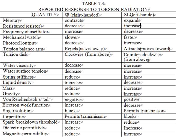
Figure1. Reported response to torsion radiation
(1) High reliability and low dark current;
(2)
Top illumination
Planar PIN PD; (3)Active
diameter 1.2*1.2 mm
The more detailed information of photodiode is in following figure2:
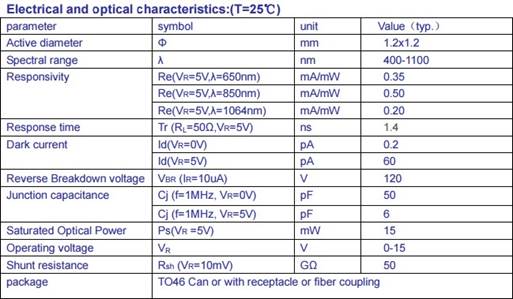
Figure2:Electrical and
optical characteristics of selected photodiode
As to the steel container, author used the dimension of the container which is designed by Mr.A.V.Bobrov in his EDL measuring system[5]. Author believed that it had good shielding effectiveness because of the thick wall of the container. The detailed dimension is and physical picture in following figure3[5]:
Figure3:The dimension and
physical picture of steel container in Mr.Bobrov's
EDL system
The photodiode should be placed into this steel container for the dark environment and the good shielding effectiveness. But before this, an auxilliary circuit is needed for the photodiode because the reverse bias voltage . In this work, the dark current should be tuned between 10-25 pA level according to tune the reverse bias voltage. The schematic is in figure4.
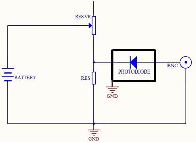
Figure4:The auxilliary circuit schematic of sensor
2.1.2. The ultra weak current meter
The ultra weak current meter in this work is in pA(10-12A) level. So the noise should be considered carefully. There are many approaches used in this work. For example, the shell of device should be well-grounded, the shielding wires should be used in all the connection and so on. And there are two points which are very important and should be noted especially.
One is that the weak current meter is different from the weak voltage meter in terms of the circuit. The larger the feedback resistance of the operational amplifier will be, the larger the theory noise will be in the circuit of weak voltage meter. But just the opposite, in the circuit of weak current meter, the larger the feedback resistance of the operational amplifier, the smaller the theory noise will be. So for the ultra weak current, a very large feedback resistance should be used without worrying about the large noise.
The other one is that the input part should be specially designed on the circuit for good isolation. For this purpose, a BNC plug is used here, because there is the PTEF material inside. The outside of BNC plug is grounded and the center of BNC plug is connected to the input area. All the wires from here should go through the air but not the surface of the circuit.
The core schematic of the circuit is in figure5:
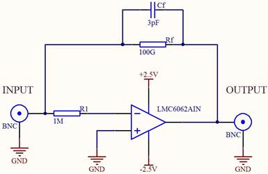
Figure5:The core schematic
of the circuit
From figure5, the circuit is a classical I/V type circuit. The selected operational amplifier is LMC6062AIN because of its low bias current which is 10fA; its low power which is 20uA and low work voltage which is 5V. The main parameter is the Ib = 10fA. The R1 is used for protection from the input part. At the feedback part, the feedback resistance is 100G and the feedback capacitor is about 3pF, so the time constant is about 0.3s. The time constant should be less than 1s because the sampling time is 1s. The theory output is 100mV/pA. There are also other types of operational amplifier can be selected, such as the LMC6042, LMP7721 and so on.
The physical picture is in figure6:
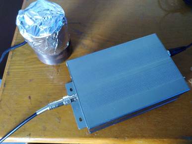
Figure6:The physical
picture of weak current meter
2.2 The magnetic rotator used in the experiments.
The magnetic rotator was suggested by Mr.V.Zamsha in the book called “Torsion Field and Interstellar communication”[8]. In this work, the whole torsion field generator system consists of one two-channel DDS generator, two 10-watt amplifiers which scale is 0- 50 KHz, and two orthogonal coils around a ferrite magnet. The impedance of two coils should be matched with the output impedance of the power amplifiers. The DDS generator can be adjusted on the computer far away to generate two channels of sine signals whose phase shift is 90 degree. Then the rotation direction of torsion field can be adjusted. The physical picture of the magnetic rotator is in figure7:
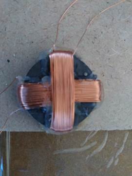
Figure7:The magnetic
generator
3. Experimental process
The first experiment. The selected torsion field generator is magnetic rotator whose direction can be switched by changing the phases of the two sine signals. The sensor is placed on the top of the magnetic rotator. The distance between the generator and the sensor of detector is about 78 mm. At the sampling circuit, one channel of A/D converter is connected to the output of the ultra weak current meter and the the data is transmitted to the computer which is a few meters away through a serial port. And the DDS which is a few meters away is also adjusted by a software on the computer through another serial port. In the process, after the recording curve became correspondingly stable, author would switch the direction of magnetic rotator on the computer and observe how the curve will change. The position of the sensor and generator is in following figure8:
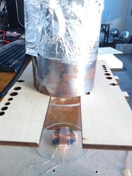
Figure8: The position between the magnetic rotator
and sensor of detector
The second experiment. In
the second experiment, a torsion field generator product designed by Mr.Shpilman is selected ( The Generator of "Axion (Spin) Field" -
"COMFORT-M5" ). It's a kind of SR type torsion field generator.
And it is powered by a Li-battery after some change. The position between the
SR generator and the sensor of detector is horizontal this time, and the
distance between them is about 85 mm. The sampling part is the same to the
first experiment. For this experiment, author mainly wants to confirm what's
said in figure1- SR can make the output of photocell decrease, using the
standard SR generator. The position between the SR generator and sensor is in
following figure9:
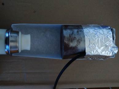
Figure9: The position between the SR generator and
sensor of detector
4. Results and discussion
4.1 Results of the first experiment
|
Figure10: The result of the first experiment |
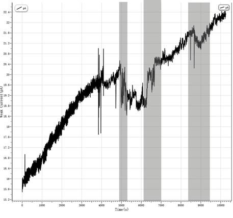
From the figure10, there are three grey areas,which indicate when the sensor of detector is impacted by the magnetic rotator, but the direction is different in each time. At the first grey area, the time range is from 4900s to 5300s, the frequencies of both signals are 10 KHz and the phase of channel 1 of DDS lags behind the phase of channel 2 of DDS exactly 90 degree for generating a right-handed torsion field. The curve obviously goes down or in other words the dark current of the photodiode decreases.Then at the second grey area, the time range is from 6120s to 7000s, frequency is same but this time the phase of channel 2 of DDS lags behind the phase of channel 1 of DDS exactly 90 degree for generating a left-handed torsion field. Correspondingly the dark current of the photodiode increases. At the third area, the signals of two channels of DDS recover to the situation of the first area for generating a right-handed torsion field, the time range is from 8380s to 9470s. We can see the trend of the dark current of photodiode is the same to the first area.
4.2 Results of the second experiment
|
Figure11: The result of the second experiment |
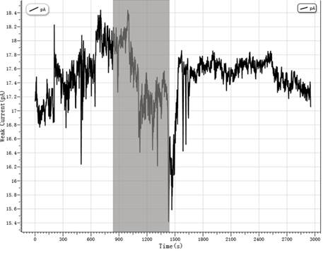
From the figure11, the grey area indicates that when the sensor of detector is impacted by the standard Mr.Shpilman's “Comfort” SR generator. In this experiment, the standard SR generator is used to confirm how the SR generator will influence the dark current of the photodiode. On the one hand, the result can be compared with the first experiment, it seems that there is the same trend of the dark current of the photodiode after impacted by the right-handed torsion field. On the other hand, the result can also confirm what the figure1 said – the right-handed torsion field can make the output of photocell decrease.
4.3 Open discussion
1.
It seems that the dark current of the selected
photodiode will change by itself along with it is used. And this phenomenon is
also confirmed by the supplier of this kind of photodiode. So
there are two points should be noted. On the one hand, if the dark current of
photodiode increases beyond the measurement range of the weak current meter,
then the feedback
resistance in the current
meter should be replaced by a smaller resistance for
larger measurement range. On the other hand, from other tests with similar
configuration, it seems that the sensitivity of the photodiode will be
different if the work dark current of the photodiode is in different level. The
tests in this work are all in the level of 10- 25pA with a new photodiode.
Different levels can be tested in further experiments.
2.
All the tests in this work, the work frequency of
the magnetic rotator is 10 KHz. The frequency range
of the selected power amplifier is 0-50 KHz. So
different work frequencies can be tested to impact the photodiode in further research.
3.
This kind of sensors based on the photodiode can
also be used to research the Psychics power and then to research the relationship
between the torsion field and the Psychics power. According to a experiment designed by Prof.Nianlin Zhu from the Yunnan University, the energy
from the special operator's palm can decrease the current of the photodiode in
the dark environment, which is opposite with the light effect. Maybe the energy
or Chi from the operator's palm is a kind of right-handed torsion field.
5. Acknowledgment
Author would like to thank Mr.V.Zamsha who suggested the design of magnetic rotator in his book called “Torsion field and Interstellar Communication”, Prof. Jinchuan Shen who lends the “Comfort” SR generator to me. Author would like to thank Lymex who is a member of the 21IC forum in Mainland China for the information about the ultra weak current meter. And author also appreciates Prof. Nianlin Zhu for some discussion on his experiment of detecting the Psychics power.
6. Reference
[2]
Gao Peng. Attempts to detect the torsion field
nature of scalar wave generated by dual Tesla coil system.
http://vixra.org/pdf/1607.0130v1.pdf
[3]Кринкер М. Инфо-индуцированные фазовые переходы и
уменьшение энтропии объекта[J]. Журнал Формирующихся Направлений
Науки, 2014, 2(1). [4]Kernbach
S, Kernbach O. On precise pH and dpH measurements[J].
International Journal of Unconventional Science, 2014, 5(2): 83-103.
[5]Бобров А В. Реакция двойных электрических слоев на воздействие торсионного поля.-М., 1997.-26 с.-Деп. в ВИНИТИ N 1055-В97[J]. ВИНИТИ. Деп, 1997 (1055-В97).
[6]
Kernbach S. Replication attempt: Measuring water
conductivity with polarized electrodes[J]. Journal of Scientific Exploration,
2013, 27(1): 69-105.
[7]
Claude Swanson. Life Force, the Scientific Basis:
Volume 2 of the Synchronized Universe
[8]
Victor Shkatov and Vitaliy
Zamsha. Torsion field
and interstellar communication.
2015.