Alexandr A.Shpilman (alexandrshpilman78@gmail.com )
"Relativistic
the charge"
Theory
|
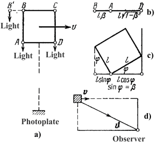
Visual observation of the cube, flying past the observer; a) The relative position
of the observer and the cube at θ = 0; b) Visible picture of a flying cube; c) A possible
interpretation of the visible picture of one observer: rotate the cube on the
an angle φ = arcsin β ; d) The observation of a flying cube angle at θ. Fig.1 |
According to the Special Theory of Relativity (STR) relativistic
density conversion of electrical discharges ρo in the transition from the
"self" of the coordinate system to the system in which the charges
are moving at a speed υ:
|
ρ1 = γ * ρo = ρo /(1-( υ/c)2) -1/2 = ρo /(1 - β2) -1/2 |
(1) |
In this case, the conversion of the volume V occupied by the charges:
|
V1 = Vo/ γ
= Vo * (1 - β2) -1/2 |
(2) |
Thus, we achieve invariance of charge:
|
q1 = ρ1 * V1 = γ *ρo Vo/ γ = ρo Vo = qo |
(3) |
Such a transformation is derived from the
example of reducing the length of the driving ruler:
|
l1 = l o/ γ |
(4) |
From which it follows that sphere flying with relativistic speeds we
will see in the form of an ellipsoid, but when you consider the time delay of
light rays coming from different points of the sphere that would be that a
stationary observer will see the sphere. Cube observer will see the cube, but
rotated by a certain angle (see Fig.1).
That is, observer will not notice the change in volume of the cube and
sphere, it would be wrong for the conversion 2 and equality 3. This means to him total charge
enclosed in the volume V increases. Because the electric field of the charges manifest itself similarly to light rays.
Violated the postulate of invariance of the charge! (I wonder why such
a focus is not taken out of the invariant mass?) As a
consequence, have a lot to revise the current foundation of physics.
Such a conclusion can be reached in other
ways. So from the
"Model of Structure Electron and Muon", should be that the
mass of the electron is fully electromagnetic nature. This means relativistic
change in mass of the electron is a corresponding change in its electromagnetic
fields and actually its electric charge.
How to check and measure the change in electric charge, for example, an
electron moving with velocity V?
For example, take the electric coil diameter of 2 cm and a height of 3 cm. Coiled copper wire 0.1 mm in diameter in two layers.
Through which an alternating current amplitude of 0.1A.
Suppose one gram mole of copper has NA = 6*1023 (Avogadro's number) of "free"
electrons. The total charge in the wires coil Q = 4 * 103 Coulomb. At
a given current in the coil 0.1A speed for electrons get Ve = 9*10-4 m/s. Changing the charge:
|
dQ = Q * (1/γ -1) ~ Q*(Ve / c)2 /2~ 2*10-20 |
(5) |
If the electrical capacity of the coil relative to its environment will
be Ck = 100 pF then the amplitude of the change in its electrical potential
will be:
|
U = dQ / Ck = 4*10-20 Kl / 10-10 F = 2*10-10 |
(6) |
Signal with a amplitude of 0.0002 microvolts
catch is not easy. Considering the quadratic dependency on the speed change in
the charge of electrons, an increase in the current pulse in the coil 10 times,
will increase the electric capacity of 100. Therefore
if metals electric current - it is not "flow" of the electrons and
their jumps, the effect can be much stronger.
The speed of electrical charge carriers in the gas above, and therefore
the effect can be higher. To test the idea is tempting to use semiconductors
with "fast" electrons.
The signal can be
enhanced by forcing the spinning reel with electric current around its
axis. If the perimeter of the coil is its linear speed Vk = 10 m / sec that:
|
dQ = Q * (1/γ -1) ~ Q*( Vk2 /2 + Vk*Ve+
Ve2 /2 ) /c2 |
(7) |
Component (Vk / c)2 /2 is equally valid for the electrons
and nuclei of atoms of the conductor. Because the amount of all charges will
zero. Component (Ve
/ c)2 /2 corresponds to the variant of formula 5. But the rest
is more interesting.
|
|
dQ ~ Q*( Vk*Ve / c2) ~ 4*10-16 Kl |
(8) |
When Ck = 100 pF from formula 6 will have the potential of
U = 4 microvolts. This is more visible.
If the ferrite core used in the coil, for example, magnetic permeability
of 1000 units, and to rotate it together with the coil is likely to change in
amplitude of the potential may be increased around 500
times. In this embodiment, the coil can be possible, and not to twist. Limited
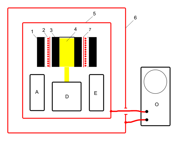
rotation of the ferromagnetic core (as in a design on Fig.2). But all this is not obvious. Pulsed current increase in the
coil 10 again to increase the electric potential at 10 times (excluding
nonlinearity ferromagnetic core).
The design of the verification of this idea, see ""Ferrimagnetic
"variant".
The idea can be checked in the embodiment
described in ""Electrostatic
"variant".
Let cylindrical electric capacitor formed copper tubes 2 and 3, has a
diameter of 2 cm and height 3cm. When the gap between the electrodes of 1 mm of
the capacitor capacitance Cc = 17 picofarads. When
the electric potential difference between the electrodes 500 volts, the
electrical charge on them is Q = 8*10-9
Coulomb. If we
give this inner liner 3 to rotate a cylindrical capacitor so that its linear velocity at the the
perimeter is Vk = 10 m/s is the formula 5 to obtain dQ = 4*10-24
Coulomb.
Alas, the result is four orders of magnitude worse than the version
with an electric current in the coil. The result can be
improved by increasing the capacitance of the capacitor using the
package plates rotating and stationary discs. Reducing the gap between the
electrodes, as well as increasing the speed of rotation. The use of dielectric
effect will not. Is that use vortices in dielectric fluids.
Experiment
|
|
|
|
"Ferrimagnetic"
version of the design
On Fig.2 shows a cross-sectional experimental
apparatus. Where ferrite tube 3, inside the electrical coil 2 is seated on the shaft 4, the electric motor D.
The electric A
battery powers an electric motor D, which rotates the ferrite tube 3. And feeds the electronics unit E, which gives pulses of
alternating current in the coil 2. The ferrite tube 1 shields the magnetic
field coils 2 and 3 ferrite tube.
Copper (aluminum) tube with a
vertical slit 7 shields the ferrite tube 3 of the electric field coil 2.
Construction placed in electrical
shield 5 which is placed in an external electrical
shield 6.
While working the device assumes the
appearance of an alternating electric potential, the observation of which is made with an oscilloscope O.
"Electrostatic" variant design
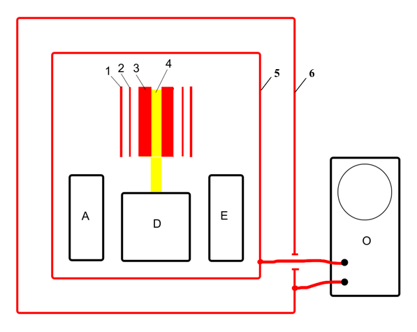
On Fig. 3 shows a cross-sectional
"electrostatic" version of the experimental device. Where copper tube
3, inside a copper tube 2, is seated on the shaft 4, the electric motor D.
An electric A
battery powers an electric motor D, which rotates the copper tube 3. And feeds the electronics unit E, which sets the pulses of
alternating voltage on the tube 2. Copper tube 1 shields the electric field
tube 2.
Construction placed in electrical
shield 5 which is placed in an external electrical
shield 6.
While working the device assumes the
appearance of an alternating electric potential, the observation of which is made with an oscilloscope O.


